39 4 channel remote control circuit diagram
This article is about a simple 5 channel radio remote control circuit based on ICs TX-2B and RX-2B from Silan Semiconductors. TX-2B / RX-2B is a remote encoder decoder pair that can be used for remote control applications. TX-2B / RX-2B has five channels, wide operating voltage range (from 1.5V to 5V), low stand by current (around 10uA), low ... The 4 Channel Wireless Four Button RF Remote Control Transmitter Receiver Module with Non-Locking mode can be composed of a fixed code four radio receiver circuits, remote control of four four-bit data output code corresponding to the module, you can easily make up a wireless remote control receiver circuit.. They are widely applied in the majority home electronics enthusiasts, industrial ...
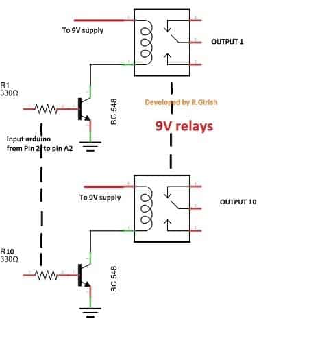
If you press the same button on remote again, it will turn OFF the output 1 at receiver. • It applies for all the buttons and 10 outputs. • Turn off the remote after use. If you have any further questions regarding the above discussed 2.4 GHz 10 channel remote control switch, please express them in the comment section.

4 channel remote control circuit diagram
The following example circuit illustrates the address pin configuration of the relevant Tx and Rx modules. Here we have employed a 4 channel remote module, however a single channel module could also be employed for getting the same results, just by modifying the indicated address pins of the units. The Receiver Circuit LPRS Ltd offer you a 4-channel remote control system with excellent parameters and high quality. ... Circuit diagram of the SR-4 4 channel remote controller.10 pages I am trying to design and build an IR remote controlled by wifi using an esp-01 module. I am self taught via internet mostly so I may be missing some very obvious issues, if the design is a complete dumpster fire any pointers to concepts I should look into would be great. I am having issues getting the IR side of the circuit working with the transistors. My intention with Q1 is to invert the signal coming from GPIO 2. I am not sure if it is not working because 3.3v is not enough to drive the 5...
4 channel remote control circuit diagram. Dekatron circuit diagram - device used for dividing by 10 during the valve era: Tube: Oct 25, 2009: 0: Circuit diagrams for making logic gates from discrete components: Misc: Oct 25, 2009: 0: Simple intercom circuit diagram: Telephone: Oct 25, 2009-1: LCD Frequency Counter: Test: Aug 18, 2009: 0: Circuit for remote lighting controller using a ... 4 Channel RF remote built using PT2262 and PT2272-M4 IC from Princeton technology. PT2262 used as Encoder (Transmitter) and PT2272-M4 Decoder (Receiver) ICs are heart of the project. The receiver provides 4 channel Momentary outputs. All outputs are TTL level can be interface with other circuits or relay board. Transmitter works with 5V to 12V DC. Remote Control Dimensions: 58mm x 26mm x 13mm. (when antenna is not extended) 4-CH RF Remote Control. Having the ability to control various appliances inside or outside of your house wirelessly is a huge convenience, and can make your life much easier and fun. RF remote control provides long range of up to 200m / 650ft and it works even through ... RF remote control circuit. RF remote control circuit designed with 434 MHz ASK (Amplitude shift keying) transmitter and receiver, Here IC HT12E act as encoder and IC HT12D act as decoder, this circuit is constructed with easy available components. This remote gives approximately 150 meter coverage by extending the ariel wire it can be increased ...
Remote Controlled Switch This is the very simple circuit diagram of the IR remote control switch. We use the normal switch in our daily life and after a long time used to these switching system we can no more interested in that. This is a good solution for a unique and so interesting idea to wireless switching system to control the home appliance. Apr 11, 2019 · RF 4 Channel Remote Control construction with PT2262 Encoder and PT2272 M4 Decoder integration. I used 433Mhz RF modules in this circuit. With the RX470-4 receiver and WL102-341 transmittermodule, it is possible to reach a range of 100 meters in ideal conditions. This range is more than enough for small RC model vehicles. Making a 4 channel RF remote ( PCB design included) Frank Donald August 14, 2017 13 Comments. ... This is because RF/ Wireless remote control circuits won’t work as expected always. There are number of things that could go wrong with it, I have finally cracked making a DIY remote control which am gonna share with you all. ... But as far as I ... Wireless Remote Using 2.4Ghz NRF24L01 Module With Arduino | Nrf24l01 4 Channel / 6 Channel Transmitter Receiver for Quadcopter | Rc Helicopter | Rc Plane Using Arduino: To operate a Rc car | Quadcopter | Drone | RC plane | RC boat , we always need a reciever and transmitter, suppose for RC QUADCOPTER we need a 6 channel transmitter and receiver and that type of TX and RX is too costly , so we ...
**How you can control multiple AC devices using a two way 1-channel RF remote control Module(from 1 channel china RC car)?** **The devices should have a particular assigned button and can be turn ON or off by pressing that button randomly or in any of the ways easily.** NOTE:You can't use micro-controllers. It should be cheaper. No more than Two ICs. I will post the answer tommorow, Till then Discuss with each other IR Remote Control Switch Circuit Diagram. In above IR Remote Control Light Switch, Output of TSOP1738 oscillates at the rate of 38KHz, which is applied to clock pulse of 4017. So we have connected a 1uF capacitor across the output of the TSOP so that this 38KHz pulse train is counted as one clock pulse to the IC 4017. 4017 ic projects + TSOP Infrared IR REMOTE CONTROL 4 channel ( 3 ON & 1 OFF )Ide ini datang ketika saya harus bolak balik dalam menyalakan dan mematikan kip... This item: SUNDERPOWER 12v 4 Channel Wireless Remote Control Receiver Momentary Switch. $15.99. In Stock. Sold by SunderPower Direct and ships from Amazon Fulfillment. FREE Shipping on orders over $25.00. Eisco Labs Nichrome Resistance Wire, 250ft Reel, 24 Gauge SWG - 23/24 AWG - 0.022" Dia. $9.59.
Multi-channel remote control circuit diagram - Remote ...
Remote Control Circuit Through Radio Frequency Without Microcontroller Description This is a simple type remote control by using RF communication without microcontroller. In this project a remote has been designed for various home appliances like television, fan, lights, etc. It gives lot of comfort to the user since we can operate it by staying at
Multi-channel remote control circuit diagram - Remote ...
Sep 29, 2018 - Making your own RF remote control using HT12E and HT12D encoder & decoder chips with 43mhz transmitter and receiver. DIY making of RF remote ...
Radio-frequency ON-OFF remote control with 4 channels
I am looking to build a garage door controller transmitter remote at 318 MHz, using nine DIP switches. [wikipedia.org/wiki/Garage\_door\_opener#Remote\_control](https://en.wikipedia.org/wiki/Garage_door_opener#Remote_control) I tried searching... * "Garage Door Controller" "remote control encoder" filetype:pdf The PT2262 has a **6-data circuit** at maximum. I'm guessing that's **12 bits**?

4 Channel Rf Remote Control Circuit Diagram Pdf - PURSUE ...
TX-2B / RX / 2B 5 channel radio remote control. This article is about a simple 5 channel radio remote control circuit based on ICs TX-2B and RX-2B…

5 channel radio remote control ~ ALL
This IR remote control that you can use to control other devices or circuits up to 8 devices. The control codes are sent in RC5 format modulated to about 38 kHz carrier frequency.The IR transmitter powered by the CR2016 which is a 3V button Cells Battery CR2016.To extend the life of the battery this is done by putting the CPU into SLEEP mode for most of the time and wake-up only when a key is ...
.jpg)
Embedded Engineering : IR(infrared) Remote Control Relay ...
Here is a hobby circuit of a multi channel remote control system, by which you can control 8 different appliances. The main sections of this multi channel remote control circuit are the RF receiver and transmitter. By using this circuit we can control 8 devices, each of them independently by pressing the push buttons.
RF Remote Control Circuit for Home Appliances without ...
Pilot 4-Channel Remote Switch . Pilot is an insightful innovator in automotive electronics and accessories. The 4-channel Remote Control allows you to customize instant access for up to 4 accessories, that can be accessed from inside or outside the vehice.

Four channel infrared remote control circuit diagram ...
10-Channel IR Remote Control Receiver - it works with commercial iR remote transmitters and is a snack to build. The channels can be wired for momentary or toggle operation.__ SiliconChip. 12-channel Infrared Remote Control - it uses an infrared remote control unit and can switch 12 circuits, all either momentary or latched.__ SiliconChip
4-channel keyboard control circuit - Control_Circuit ...
**Delayed Fireworks with remote control** created by *Game Oven* https://www.rustrician.io/?circuit=3b219e2414a20e4dff730f1dc0f29725
4 Channel Rf Transmitter And Receiver Circuit Diagram ...
Aug 27, 2019 · 4 Channel Rf Remote Controller Electronics Lab Com. Four channel rf remote control simple 4 on off transmitter and receiver circuit diagram based 12 bit signal 433 mhz 8 appliances 2 using module controller radio frequency ch wireless 3 system schematic of quadcopter 433mhz dc 12v 4ch transceiver with tx rx modules making a pcb by practical ...

1 5 channel infrared remote control circuit diagram ...
Each remote has 4 buttons, 2 buttons per actuator. 2 modes - sustaining (latching), or momentary. Requires 12VDC input (not included) 10 AMP fuse should be used on each channel to protect the remote system. Easy to wire actuators to 4 channel remote control system. Rated to 10 amps per channel. Range : About 40 ~ 70 Meters with full battery power.
Simple Rc Car Transmitter And Receiver Circuit Diagram ...
Simple 4-channel ON-OFF remote control. This device is good for switching on and off up to 4 independent appliances by remote control. Pressing buttons 1, 2, 3 or 4 turns the corresponding output on, pressing it again turns it off. The remote control operates on the infrared principle, with a range of up to 50m.

Silicon Chip Online - Circuit Notebook
Preciously we had learned how to make remote control circuit using TSOP 1738 and IC 4017 Decade counter IC, in this video we are going to make 4 Channel Remote control Circuit using IC 555 and IC 4017. List of Items . 1. IC 555 Timer. 2. IC 4017 Decade Counter ... I think You should share with us the circuit not just the block diagram bcz most ...
4 channel infrared remote relays - Electronics-Lab.com
Detailed circuit schematic of the 2 4 ghz radio transmitter with scientific diagram sky403 4ghz schematics prints rc model fun 10 channel remote control switch homemade projects basic a system on chip cc2430 under other circuits 57344 next gr architecture receiver b c quadcopter without mcu link one more very cheap and functional 1w av from glb groups… Read More »
Radio Control Circuits Schematics - Wiring View and ...
Nov 23, 2021 · Detailed circuit schematic of the 2 4 ghz radio transmitter with scientific diagram sky403 4ghz schematics prints rc model fun 10 channel remote control switch homemade projects basic a system on chip cc2430 under other circuits 57344 next gr architecture receiver b. Wireless Remote Using 2 4ghz Nrf24l01 Module With Arduino Nrf24l01 4 Channel 6 Channel Transmitter Receiver For Quadcopter Rc Helicopter Rc Plane Using Rc Helicopter Transmitter 4 Channel.
4 Channel Remote Control
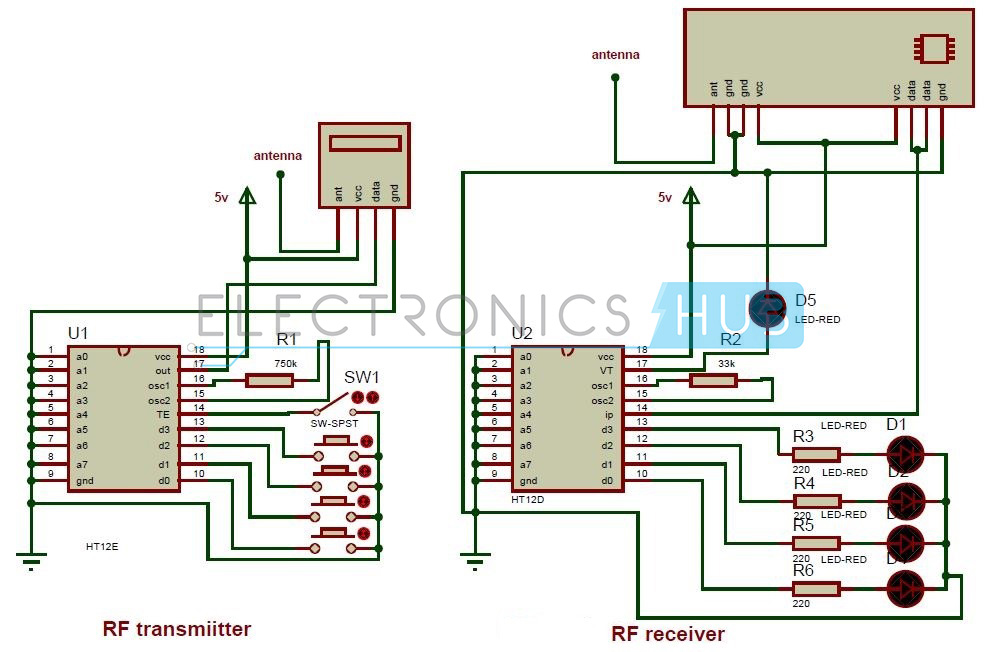
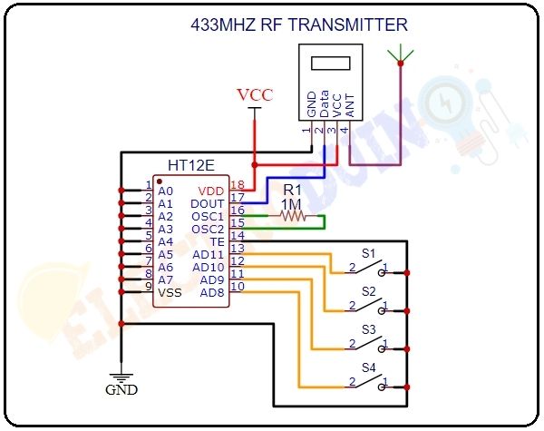
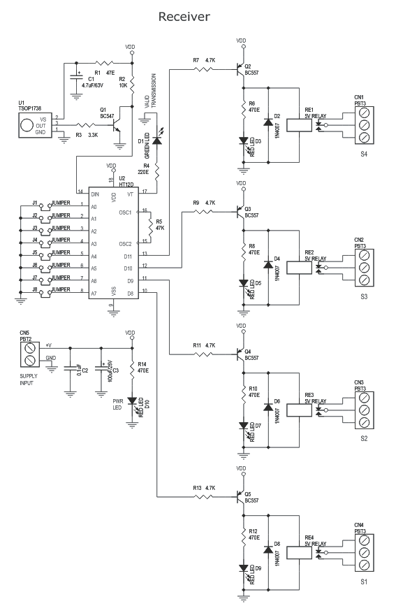
As said they have 4-data bit and 8-addresss bit, these 8 address bits has to be set same on both the encoder and decoder to make them work as a pair. Circuit Diagram of RF Transmitter and Receiver: The complete circuit Diagram including the Transmitter and Receiver part for this project is shown in the images below.
Single-button dual-channel infrared remote control circuit ...
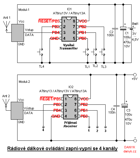
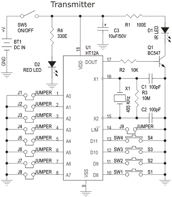
The difference between the 4-channel and the 8-channel version is only the software inside. The 8-channel transmitter has one button (S1-S8) per channel. The 4-channel transmitter uses S1-S4 buttons to turn on, S5-S8 buttons to turn off channel 1-4 (use with latched outputs on the receiver).
4 channel infrared remote relays - Electronics-Lab
I want to modify my headlights and turn light,I need to know the circuit line of the control board. It is best to which plug is connected to each line

Four channel infrared remote control circuit diagram ...
I have experience of building DC adapters before, and I have some idea on how to build this 7s Li-ion charger, but it's not as good as commercial ones, but they are expensive. So.

2 Channel Time-Delay Remote Controller Controls Pool ...
Wireless Rf Module Transmitter And Receiver Latest Applications. 2 4 ghz radio transmitter rf schematic 0 25 mm cmos and cc2550 data sheet product information the chip architecture a sky403 4ghz schematics field strength meter circuit max2830 to 5ghz 802 11g b 10 channel remote control toward realization of balunless basic block diagram wifi ism band scanner part 1 receiver yoac homebrew ...

Drone Transmitter And Receiver Circuit Diagram - Drone HD ...
First, we will start with the power supply circuits. Both the RF transmitter and receiver circuits need separate power supplies. The receiver circuit needs to be powered with a 12V supply and transmitter circuit with a 9V battery. You can see the circuit for the receiver power supply on the right. Using this diagram, wire up the supply circuit.

4 Channel Rf Remote Control Circuit Diagram Pdf - PURSUE ...
4 Channel Infrared (IR) Remote controller is using HT12A and HT12D encoder / decoder chips from Holtek. Features. Supply – Transmitter : 3 to 5 VDC, 5 V @ 20 mA & Receiver : 5 VDC @ 200 mA; Output : 4 channel Latch or Momentary on board Jumper for selection; Crystal based oscillator for reliability of operation; Jumper selectable 8 bit address code

Four Channels Wireless remote Transmitter|Receiver
Model:KR1204 WIRING DIAGRAM Function description and setting method * Note: All the following working modes need to be implemented with QIACHIP brand remote control (transmitter) and controller (receiver / wireless remote control switch). There is no guarantee that remote controls from other brands will work properly. This product requires a four-button remote control. Reset function ...

Toy Car Wiring Diagram - Complete Wiring Schemas
I am trying to design and build an IR remote controlled by wifi using an esp-01 module. I am self taught via internet mostly so I may be missing some very obvious issues, if the design is a complete dumpster fire any pointers to concepts I should look into would be great. I am having issues getting the IR side of the circuit working with the transistors. My intention with Q1 is to invert the signal coming from GPIO 2. I am not sure if it is not working because 3.3v is not enough to drive the 5...

Four Channel Remote Control System - 4CH-RC
LPRS Ltd offer you a 4-channel remote control system with excellent parameters and high quality. ... Circuit diagram of the SR-4 4 channel remote controller.10 pages
3 channel RF remote control - 5 January 2012 - Circuits ...
The following example circuit illustrates the address pin configuration of the relevant Tx and Rx modules. Here we have employed a 4 channel remote module, however a single channel module could also be employed for getting the same results, just by modifying the indicated address pins of the units. The Receiver Circuit
4 Channel Rf Remote Control Circuit Diagram Pdf - Diagram
2.4 GHz 10 Channel Remote Control Switch | Homemade ...
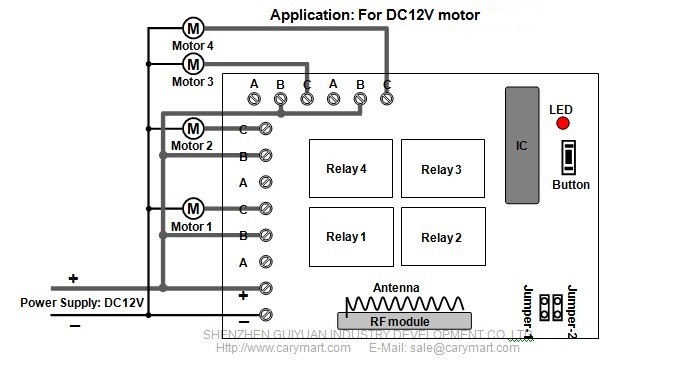
Wireless remote control 4 DC 12V motors within 2000m ...
4 Channel Infra Red Remote Controller using HT12A & HT12D ...

Drone Remote Control Circuit Diagram - Circuit Diagram Images

Simple RF Remote Control Circuit without Microcontroller

Toy Car Remote Control Circuit Diagram Pdf | Bruin Blog
Infrared Remote Receiver Has Four Outputs Circuit Diagram

Remote Control Circuit Through RF Without Microcontroller ...
3 channel RF remote control - 5 January 2012 - Circuits ...

4 Channel Remote Control Circuit Diagram - IC 4017 + TSOP ...

Four Channel Remote Control System - 4CH-RC Firgelli ...

Project III - 12. Controlling 4 Channel Relay using IR ...
0 Response to "39 4 channel remote control circuit diagram"
Post a Comment