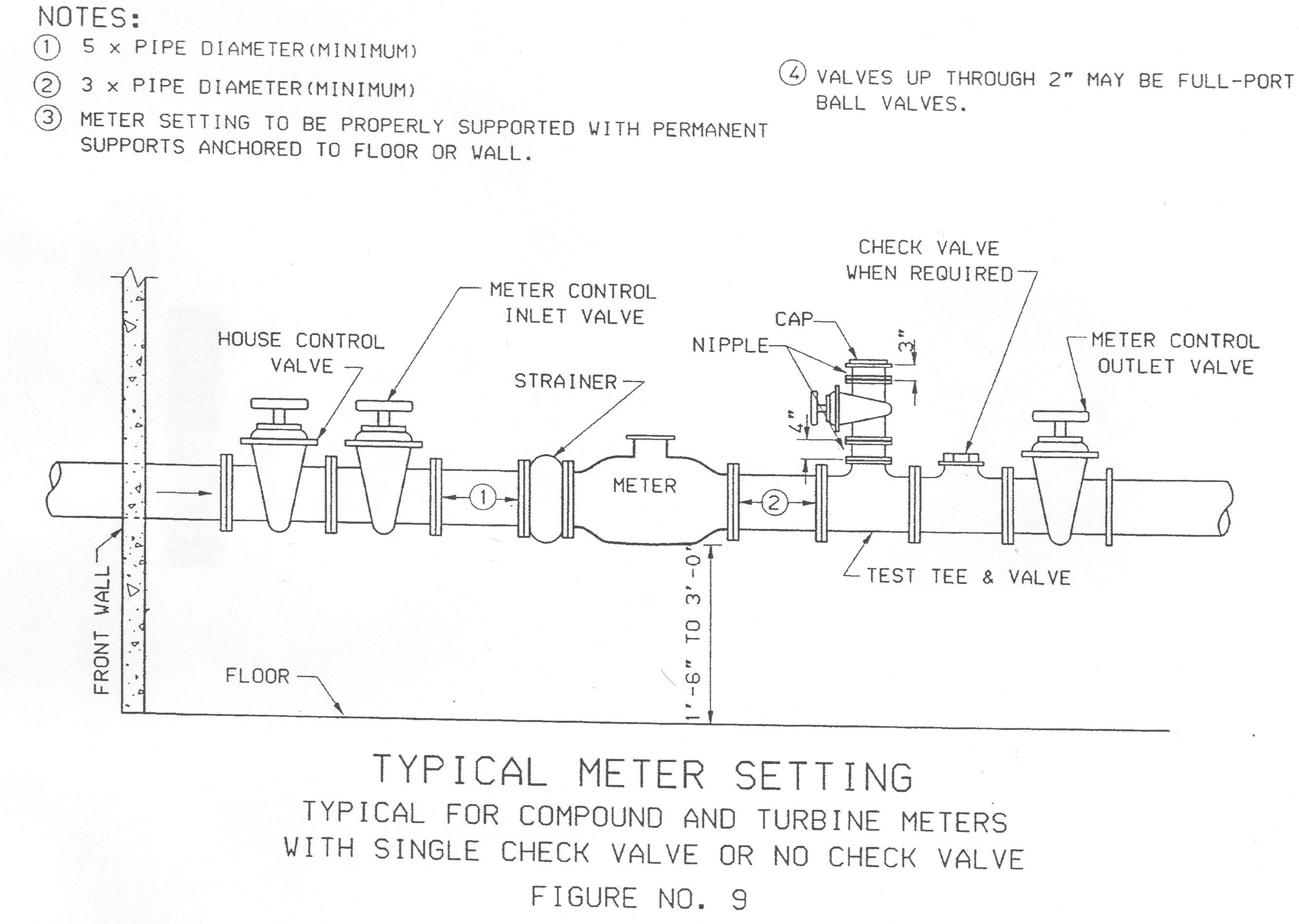
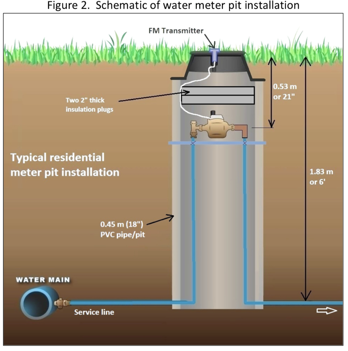
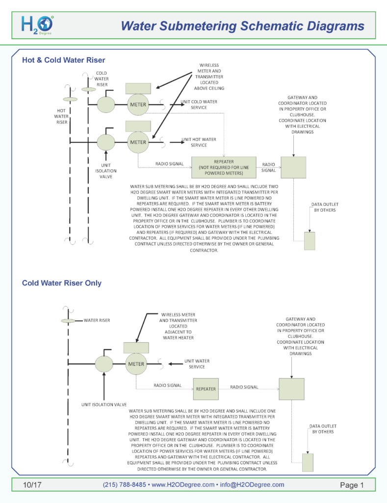
37 water meter connection diagram
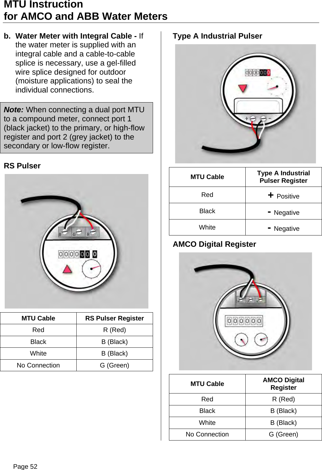
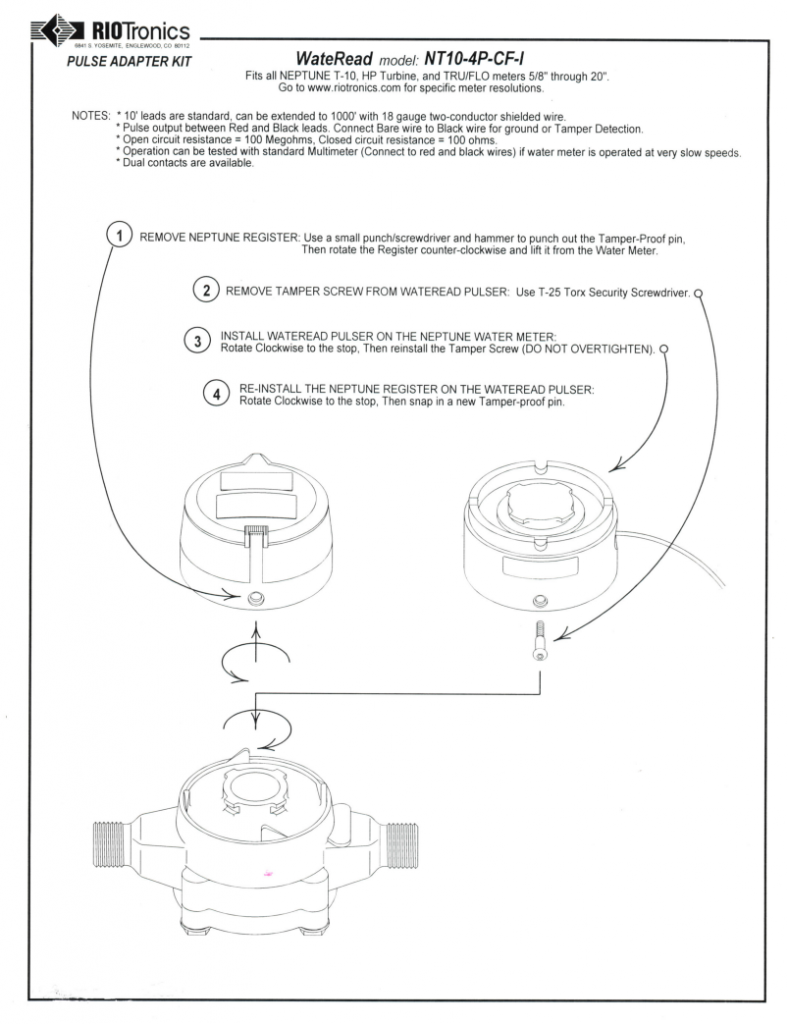
Water Meter Pulse Outputs. Order as "NT10-4P-CF-I" For Neptune water meters, integrating Neptune T10 water meters with submersible, high resolution, and easy to install digital outputs, WaterRead features a one size fits all T10, Tru/Flo (R) and HP Turbines. Form A digital output is high resolution, and can be easily field retrofitted. - Meter panel fuse not required for an overhead supply. - Off Peak controlled load only includes single phase hot water & single or multi-phase storage heating. - Wiring diagram applicable for Solar. - Metering diagram is applicable for 2 or 3 phase load. For 2 phase loads - Red and Blue phase is preferred.
the meter relocated outside the customer's facility near both the SMART production meter and the utility disconnect switch. Note 2 * Must have a cellular connection at meter location. * Meter will have bi-directional interval recording capabilities. * Secondary metering CTs/VTs may be required. Note 3

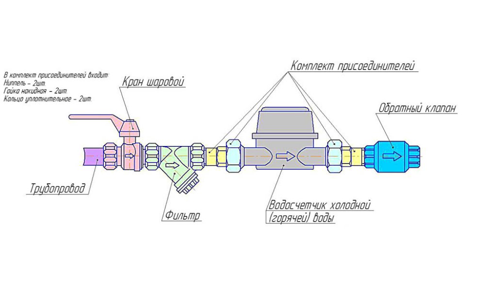
Water meter connection diagram
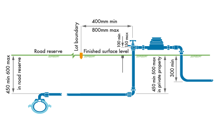
Check the water meter for the proper direction of flow. The meter will have some kind of flow direction indicator located on the top or sides of the meter. Then install the new meter and rubber gaskets. For proper installation, never use a wrench to start the thread connections. Always start the meter connections by hand to make sure that the ... refer to the Annexure - Standard Water Meter Connection Schematic Diagram - Types 1 to 5 Diagrams and Types 3A to 6 (TSS-001 and TSS-002). 3.2.2 Connection to the Water Main, Property Water Service and Water Meter Sizing for Dual Occupancies and Granny Flats Developments (new and reconfigured) which fall between a single residential dwelling Oct 11, 2018 · The TRICON® transmitter provides an electronic interface to Neptune water meters, enabling customers to monitor their water usage and control various processes based on that usage. The appropriate wiring diagram. Refer to Figure and Table for the wiring diagram. Jan 14, · Identify Which Meter Type You have. If it has Wiring Built-In, Follow ...
Water meter connection diagram. Do-it-yourself water meter installation: technology, rules, diagram. The cost of goods and services is constantly increasing. Installing water meters will ... WIRING DIAGRAMS For technical questions, call 952.492.8330 To schedule Energy Wise/Off Peak meter installation, call 952.492.8255 These diagrams are for reference only. The manufacturer's connection requirements for the Demand Response Unit (DRU) shall be followed. MVEC is not responsible for these connections. d-23 new copper 1-inch water service standard meter vault d-24 new copper 1.5 n. & 2 in. water service standard meter vault d-25 3 inch, 4 inch, 6 inch, 8 inch & 12 inch meter vaults d-26 12 inch meter vault with check valve d-27 typical meter installation for 1 inch water service with lawn hydrant and backflow preventor Wiring diagram of hot water meter. Installation of water meters by one's own hands: technology, rules, scheme. The need to install a water meter against the ...
connections between sensor and transmitter are completed by the manufacturer. For remote version, the connections can be done by the manufacturer as well, if user requests. R. efer . to the following diagrams for wiring in transmitter junction box. Diagram A ~ E are the connections for outputs. terminals in the flow meter. See Figure 7. A wiring diagram decal is located adjacent to the field wiring terminals within the FUSION enclosure. If the flow meter is only to be utilized as a flow rate indicator or totalizer, no further wiring will be required. Skip to the Flow Meter Configuration section of this manual (see page 19). Flow meter connection Diagram | Flow meter ka connection kaise kare | water flow meter kaise lagaye|Aaj ke is video me bataya gaya hai ki aap water flow mete... • Continuity of the grounding path shall not rely on water meters or fi ltering devices or similar equipment according to 250.53(D)(1) of the Code. Bonding jumpers shall be connected around meters, fi ltering devices and similar equipment. • If metal underground water pipe is used as the sole grounding electrode system,
The meter must be installed in a clean pipeline, free from any foreign materials. The meter must be inserted with the flow in the direction of the arrow molded, or cast, into the meter body. Meter may be installed in horizontal or inclined lines. Couplings are provided, which allow for connection with NPT threads in sizes 1/2" thru 1". The A water meter is generally ¾ inch, but there are exceptions. Get a backflow preventer and a thermal expansion control device and place them on the end of the pipe according to plumbing code. Step Four - Obtain the Meter. You’ll need to get a water meter from either the municipality or by purchasing it online. Meter 1/4" 74 micron / 200 mesh. Meter 1/2" - 2" 250 micron / 60 mesh. Meter 3" - 4" 400 micron / 40 mesh. 5. Note: The Flowmeter can accept flow in any. direction. 6. The meter can be installed in any orientation as long as the meter shafts are in a horizontal plane. (Refer to diagram below for correct installation). Note: WR-04 Recycled Water Irrigation Cross Connection Test Station (01-26-2022) Updated; WR-05 Temporary Potable Water to Recycled Water Inter-Connection (03-01-2001) WR-06 75mm (3") or Larger Recycled Water Irrigation Wye Strainer & Check Valve Installation (09-12-2008)
Cathodic Protection Wiring Diagram W-0850 3” & 4” Compound Meter Installation W-0860 3” Turbo Meter Installation W-0870 Typical Plan Layout Sewer Systems W-1000 Typical Pipe Bedding Vitrified Clay Pipe Extra Strength W-1010 Concrete Arch W-1020 Classes "BB", "B", "C" & "D" Beddings W-1030 Concrete Encasement W-1040
Aug 26, 2018 · INSTALLATION. • AMI INFRASTRUCTURE Install new meter; turn water on. Mount MXU to Sensus ECR (all variants). Green. Red. Black. for Sensus and Invensys Water Meters provides wiring information for use in connecting a STAR MTU to Sensus Step 2 – Select the wiring diagram that. for Sensus and Invensys Water Meters provides wiring information for use in connecting a STAR MTU to Sensus Step 2 ...
Water Supply Fixture Units (WSFU) and Minimum Fixture Branch Pipe Sizes. Important notes: Appliances, appurtenances, and fixtures not referenced in the table below shall be permitted to be sized by reference to fixtures having a similar flow rate and frequency of use. The listed fixture unit values represent their load on the cold water building supply.
24 Jul 2020 — Step By Step guide to installation of water meters · Test the meter before installing it · Install a meter in a way that the flow of water flows ...
This helpful instructional video will help you learn how to correctly install a water meter. For more information, http://austintexas.gov/department/taps
See Appendix 1 - Diagram 2 (page 8) which shows an illustration of a typical single meter installation of in-line meter internal (not on manifold). Diagram 3 (page 9) shows, a meter carrier for a single and/or multiple internal meter installation (which can also be used on a multiple manifold).
Arad Water Meter Brochures . Multi-Jet Magnetic Water Meter (785 KB) Sonata Dual Pulse Water Meter (680 KB) Munters. Greenhouse . Green Field Brochure (2 MB) ... WOD Pro Rotem Platinum Plus/ XL50 Wiring Diagram (516 KB) WOD Installation 2012 (164 KB) WOD Initial installation instructions (380 KB)
00:30 Meter Connection Step 1 Using the shovel, carefully uncover the property side of the water meter. Make sure you have plenty of room to work around the meter. Step 2 With the pipe wrench, remove the cap or existing pipe from the water meter. Make sure dirt and debris do not get into the exposed end of the meter. Step 3
You need this material: *- A water meter (of course!) in mi case a 3/4 new generation polymer home water meter. *- 1st step water filter (this can be removed) but i considered usefull. *- 2 3/4 galvanized union nut. (it can be copper but it´s more expensive) *- 2 3/4 copper elbows. *- 1 3/4 copper elbow with rope. *- 4 3/4 copper weldable coupling. If you removed water filter only use 2. *- 3 ...
neptune water meter wiring diagram - What's Wiring Diagram? A wiring diagram is a type of schematic which uses abstract pictorial symbols to show every one of the interconnections of components in the system.
remove the water from the water meter as the backflow preventer will not allow the meter to drain. If the meter is exposed to freezing conditions, the sacrificial frost plate (#2 on the diagram) will break to prevent damage to the meter. Frost plate repairs must be completed by the municipality and the costs are billed to the home owner ...
the meter for close coupling, the included couplings are much preferable because they provide a union connection for meter service. Be sure to use the included gasket between the end of the meter and the coupling. Connections. PR and PT sensors are supplied with a color coded output cable (see diagram, page 4). Optional connec-
Sensus Products WP Dynamic 50 °C Water Meter from how to install water meter diagram In case the gauge is not functioning, retest the connections. An air fuel gauge will enable you to monitor the changes in oxygen content in the air your car or truck is breathing so you can make adjustments to prevent damage to your car or maybe to stop poor.
Water Meters. Water Meters; Clearance Items ... 800-654-0821. Wiring Diagrams. Not all installations are created equal. Search through our list of wiring diagrams to find the right one for your job. Single Phase – Form 2S for 120V Circuit. FORM 2S Need a meter for a 120 volt circuit? Order our 240 volt meter. This diagram shows how to wire it ...
used for both inside and pit-set utility meter installations to provide safe, off-site meter reading. • The MXU provides the industry's only two-port radio interface device. In addition to the two-port design, the MXU is compatible with the MultiRead™ Module that permits two, four, or eight meter connections per MXU port.
Oct 11, 2018 · The TRICON® transmitter provides an electronic interface to Neptune water meters, enabling customers to monitor their water usage and control various processes based on that usage. The appropriate wiring diagram. Refer to Figure and Table for the wiring diagram. Jan 14, · Identify Which Meter Type You have. If it has Wiring Built-In, Follow ...
refer to the Annexure - Standard Water Meter Connection Schematic Diagram - Types 1 to 5 Diagrams and Types 3A to 6 (TSS-001 and TSS-002). 3.2.2 Connection to the Water Main, Property Water Service and Water Meter Sizing for Dual Occupancies and Granny Flats Developments (new and reconfigured) which fall between a single residential dwelling
Check the water meter for the proper direction of flow. The meter will have some kind of flow direction indicator located on the top or sides of the meter. Then install the new meter and rubber gaskets. For proper installation, never use a wrench to start the thread connections. Always start the meter connections by hand to make sure that the ...







0 Response to "37 water meter connection diagram"
Post a Comment