39 carburetor fuel system diagram
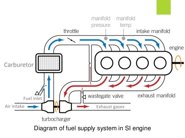
Fuel System Diagrams - Aeromotive, Inc. Select CARB or EFI Carbureted Fuel Injected. Select Power Adder No - Naturally Aspirated Yes - Forced Induction. Select FUEL Gas E85. Mounting Configuration External In Tank. Step 1: Fill out pump finder above. Step 2: Add the pump to your cart. Step 3: Refer to the diagram on the product page for ... Carburetor. A device in an engine for automatically mixing fuel and air in appropriate ratios to produce a combustible gas. Atomization or Vaporization. The process of transforming a substance from the liquid state to the gaseous state. This is an important process for the proper running of an engine. Governor.
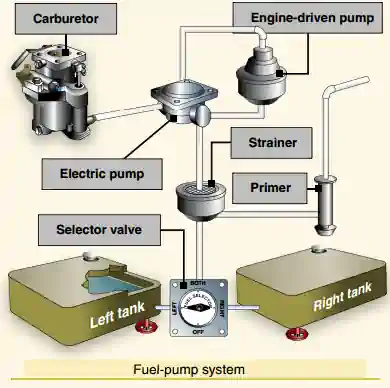
Holley performance carburetors are equipped with a fuel bowl that is designed either for a center pivot or a side pivot float. An externally adjustable needle and seat assembly is used so that the float level can be easily adjusted without the need to disassemble the carburetor. Fuel Inlet System. Center Pivot/Hung Float. Fuel Inlet System.

Carburetor fuel system diagram
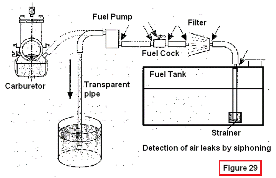
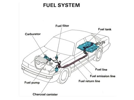
FLOAT SYSTEM The Quadrajet carburetor has a centrally located fuel chamber in the float bowl (Figure 5). The fuel chamber is centered between the carburetor bores to assure an adequate fuel supply to all metering systems with respect to car inclination or severity of turns. The float system (Figures 6 or 7) consists of a fuel When carburetors were the primary means of metering fuel to the engine, the fuel delivery system was easy to understand: It consisted of a tank, a fuel line ... A fuel pump draws the fuel from the tank through fuel lines and delivers it through a fuel filter to either a carburetor or fuel injector, then delivered to the ...
Carburetor fuel system diagram. In Line Pump in. Carburetor Application. Carburetor Swivel Pump. Belt Drive Diagrams. Belt Drive Dual Carburetor. Belt Drive EFI. Fuel for testing on the roller dynamometer is supplied through the car fuel pump system, and this is a check that the flow is adequate. A test should also be carried out with the correct carburetter dampers fitted to ensure that they in no way affect the tuning. Road tests. Both engine and dynamometer tests are carried out with the one object of obtaining optimum performance from the vehicle ... 31 Mar 2008 — can anyone help with a 73 240z fuel system diagram ? assembley diagram stout racing engines www.stoutracingengines.com (423) 715-3897 . e-1 crankcase ref. no. part number description 1 26329/168f washer 2 26321/168f split pin 3 26311/168f regulating sway bar 4 gb276-89 bearing 6205 5 11213/168f washer 6 11212/168f drain plug 7 13180/168f oil seal, crankshaft 8 11100/168f crankcase 9 gb6177-86 nut m10 10 37810/168f oil sensor 11 gb5787-86 bolt ...
Fuel pressure in a static system is always maintained higher from the fuel pump to the regulator (typically 12-60 psi) than it is from the regulator to the carburetor (8-9 psi). 24 Nov 2015 — The carburetor is responsible for mixing gasoline and air together in just the right amounts and getting that mixture into the cylinders. FUEL SYSTEM/CARBURETION Jet Part Numbers Whenever servicing the carburetor or fuel system, it is important to heed the following warnings. A WARNING Gasoline is extremely flammable and explosive under certain conditions. Always stop the engine and refuel outdoors or in a well ventilated area. 925 Posts. #6 · Feb 28, 2012. You can run a return-style regulator one of thw ways. The more traditional (for carb) method is to deadhead the carb, by placing the regulator upstream of the fuel log (see first pic). The disadvantage to this setup is that there is stagnant fuel in the fuel log, and this can cause vapor lock and fuel boiling ...
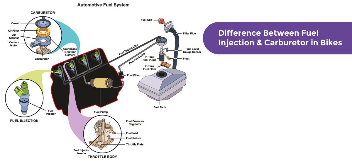
Chuck Nuytten Carburetors - Plumbing Diagrams. Fuel System Plumbing Diagram. Fuel System Order List. Fill out these charts to be sure that you have everything necessary to plumb your car. 13 Sep 2016 — When using pumps rated above 8psi a regulator is required to keep the carburetor from flooding. Note: On many vintage carburetors such as ... QFT™ carburetors are 100% tested to ensure all components are functional. The calibration should be very close for all adjustments. Different engine combinations could require adjustment of idle mixture, idle speed and main jets. The fuel level was set with 6 ½ lbs. of fuel pressure. The recommended fuel pressure for this carburetor is 6 ½ PSI. Illustration of Automotive Fuel System infographic diagram showing parts of carburetor injector throttle body from tank to engine process for mechanics and ...
Mixers & Carburetors Woodward’s Streamline™ fuel system products are easy to select and easy to use. A broad selection of Streamline mixers, carburetors, regulators, vaporizors, and fuelocks cover a wide range of gaseous engine applications, from 50 to 400 horsepower. Streamline™ N-VFF30 Series fuelock filters are
A fuel pump draws the fuel from the tank through fuel lines and delivers it through a fuel filter to either a carburetor or fuel injector, then delivered to the ...
When carburetors were the primary means of metering fuel to the engine, the fuel delivery system was easy to understand: It consisted of a tank, a fuel line ...
FLOAT SYSTEM The Quadrajet carburetor has a centrally located fuel chamber in the float bowl (Figure 5). The fuel chamber is centered between the carburetor bores to assure an adequate fuel supply to all metering systems with respect to car inclination or severity of turns. The float system (Figures 6 or 7) consists of a fuel

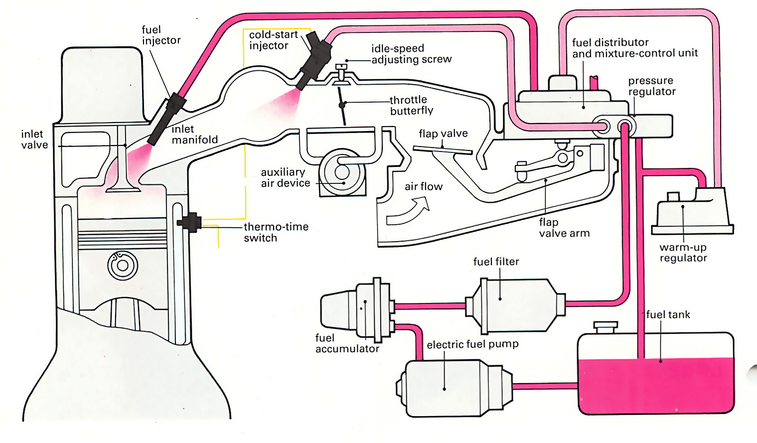
Automotive Fuel System Infographic Diagram Showing Parts Of Carburetor Injector Throttle Body From Tank To Engine Process For Mechanics And Road Traffic Safety Science Education Royalty Free Cliparts Vectors And Stock Illustration
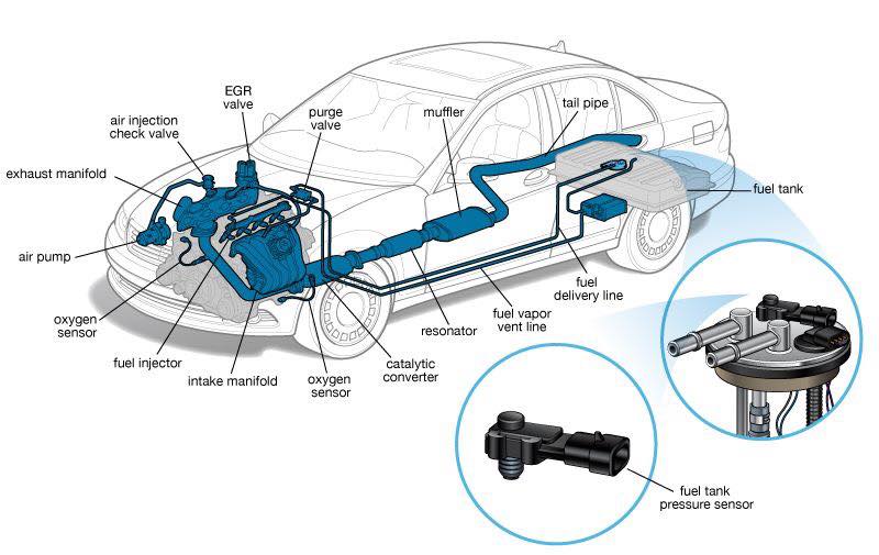
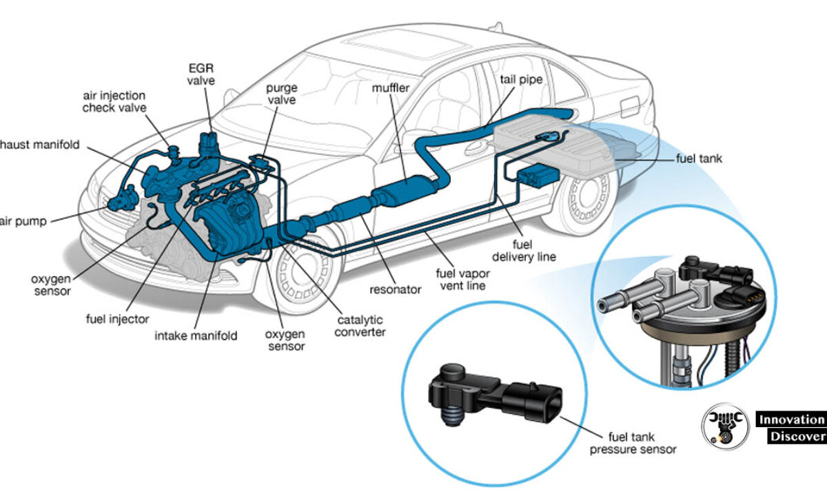
Fuel System Components Working Principles Symptoms And Emission Controls Ingenieria Y Mecanica Automotriz










0 Response to "39 carburetor fuel system diagram"
Post a Comment