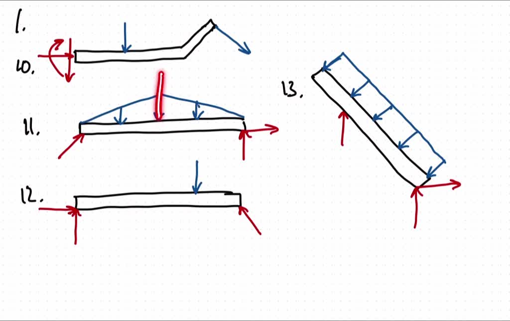
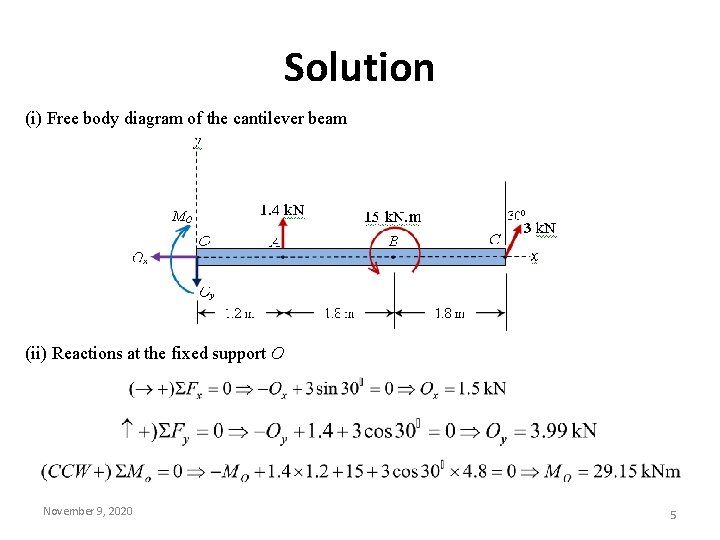
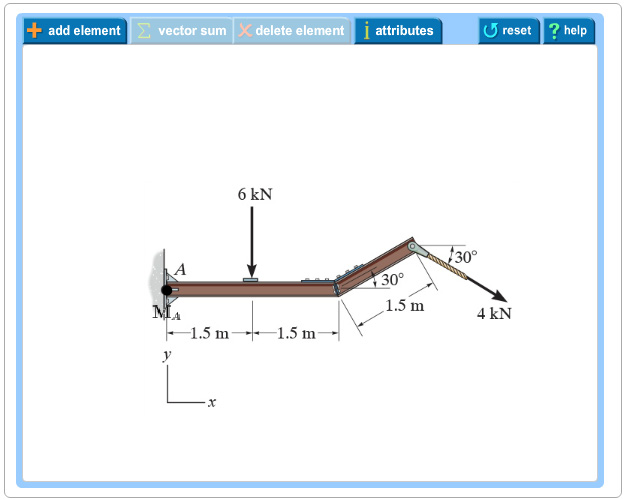
37 draw the free-body diagram for the cantilevered beam. a is the a fixed support.
A is the a fixed support. Draw the vectors starting at the black dots. The location and orientation of the vectors will be graded. The length of the vectors ... Universal Beams Table 14 Universal Beams - Properties for Assessing Section Capacity Designation Yield Stress Form Factor Abo Note: The Z x is the section modulus. It is the second moment of area (I) divided by the distance from the neutral axis (y max ). It will help you find the right size steel beam. 1. Draw free-body-diagram (FBD) 2.
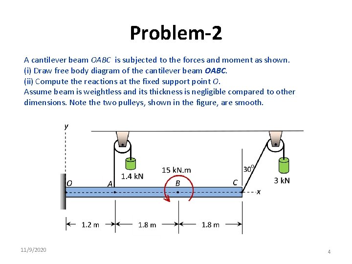
2 Example Learning Objective: 1) Draw Free Body Diagrams (FBDs) for a structure consisting of multiple rigid bodies. ... (Beam Bending, Yield criteria) A circular cantilever beam (AB) is connected to a handle as shown below. At the end of the tip(C) of the handle, Spiderman is hanging. Due to his weight (W), this str ... Determine the support ...
Draw the free-body diagram for the cantilevered beam. a is the a fixed support.
Part A Draw the free-body diagram for the cantilevered beam. A is the a fixed support. Draw the vectors starting at the black dots. The location and orientation ... Soft rock slopes were anchored with traditional steel bars and new Glass Fibre Reinforced Polymer (GFRP) bars. The difference in the anchorage performance of the two kinds of anchorage elements in soft rock and expansive soil was studied by an in-situ test. The results show that cyclic load can aggravate the bond damage of the interface between grouting body and both kinds of bars used in soft ... Step 2: Make a cut along the members of interest. Here comes the most important part of solving a truss using the method of Sections. It involves making a slice through the members you wish to solve. This method of structural analysis is extremely useful when trying to solve some of the members without having to solve the entire structure using ...
Draw the free-body diagram for the cantilevered beam. a is the a fixed support.. To maximize the efficiency of the structure (which is often measured in the material used or labor), an appropriate truss type should be selected for the design. Today we will explore what types of truss structures are out there and how they can benefit your design. Pratt Truss. Warren Truss. K Truss. 1.Draw Free-Body Diagram 2.Defined Coordinate System 3.Label All Forces 4.Apply Newtons 2nd law 5.Use uniform Circular motion 6.Solve for Tangential Velocity tano-us Note: if pls > tand then Vmin = 0 Vmin gr 1+Mstano tano+lis Vmax Vgr and if Mstand > 1 then there is no Vmax 1-Mstand Example: If a curve with a radius of 50.0 meters is banked at ... For each beam configuration, there are, on average, five example calculations presented to include finding support reactions, shear force and bending moments, and deflections. This means there are chapter 2: beams reactions, shear force and bending moment distributions, and deflections (a)A simply supported beam of a span 7 m carries a udl of 5 KN/m over 4 m length from the left support and a point load of 50 KN at 2m from the right support. Draw SF & BM diagram. ( b) A Cantilever of span 3 m carries a udl of 4 KN/m over entire...
Shading this basic introduction to shading will help you to begin to add the depth to your drawings that they need to really pop out of the page. Abstract drawing if you are looking for a new outlet for creative ability and you haven't ever done an abstract drawing, read this article now! pastel drawing info on the tools and technique of pastel . In this lesson, students learn the basics of the analysis of forces engineers perform at the truss joints to calculate the strength of a truss bridge. This method is known as the "method of joints." Finding the tensions and compressions using this method will be necessary to solve systems of linear equations where the size depends on the number of elements and nodes in the truss. The ... The re for e the bending moment diagram is: Example 2 Draw the shear for ce and bending moment diagram s for the beam show below: a) determine the reactions at the supports Taking moments about A (clockwise moments = anti-clockwise moments) (10 x 6) x 3 = 6RC where 10 x 6 =60kN = total load and 3m =distance from A to where the load is acting ... Part A Draw the free-body diagram for the cantilevered beam. A is the a fixed support. Draw the vectors starting at the black dots. The location and orientation ...
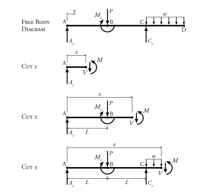
Once you have the reactions, draw your Free Body Diagram and Shear Force Diagram underneath the beam. Finally calculating the moments can be done in the following steps: 2. From left to right, make "cuts" before and after each reaction/load. To calculate the bending moment of a beam, we must work in the same way we did for the Shear Force ... Transcribed image text: Part A Draw the free-body diagram for the cantilevered beam. A is the a fixed support Draw the vectors starting at the black dots. Spacecraft Structures Jacob Job Wijker Spacecraft Structures With 199 Figures and 106 Tables iv Jacob Job Wijker Dutch Space BV P.O. Read Ebook Tajweed Diagrams I and II Combined Arabic Edition - Khadeejah Akyurt PDF 20.11.2021 By xabij Tajweed Diagrams I and II Combined English Edition Akyurt
Solved Equilibrium Of A Rigid Body Engineering Mechanics Statics And Dynamics 14th Physics Numerade
Find the reactions at the fixed support A. This problem has been solved! See the answer ...

Cantilever Beam Shear Force And Bending Moment Diagram With Triangular Load Youtube
By using instead the "Beam-Beam" option, I can input both the axial force and the bending moment but I am not allowed to use the CHS section. In fact, if I want to create a new section in the "New section definition" tab, it seems I can chose only standard UC - UB sections and not allowed to create a CHS user section.
Solved Draw The Free Body Diagram For The Following Problems A The Cantilevered Beam In Prob 5 10 B The Beam In Prob 5 11 C The Beam In Prob 5 12 D The Beam In Prob
Bending Moment Equations and Formulas offer a quick and easy analysis to determine the maximum bending moment in a beam. Below is a concise table that shows the bending moment equations for different beam setups. Don't want to hand calculate these, sign up for a free SkyCiv Account and get instant access to a free version of our beam software!

Pdf Shear Forces And Bending Moments Md Shahin Alam Academia Edu
motogurumag.com is an online resource with guides & diagram s for all kinds of vehicles. If you look for a fuse box diagram, timing belt diagram, or maybe wiring diagram - this is a place for you. We also have over 350 guides & DIY articles about cars. 2 Jul 2015 — C3 Tech/Performance - 1982 Fuse box (under dash): Pics or list of ... I ever saw had a pic\ diagram of the fuse block and a ...

Bending Moment And Shear Force Diagram Of A Cantilever Beam
A is the a fixed support. Draw the vectors starting at the black dots. The location and orientation of the vectors will be graded. The length of the vectors ...
Mechanics Map Bodies And Free Body Diagrams
Generally, all types of machinery are provided with supports for rotating shafts, the supporting device is known as a bearing.In other words, a bearing is a machine element that constrains relative motions and is used to reduce the friction between moving parts.. Bearing employs to support, guide, and restrain moving the element.
4 3 Determinate Beam Analysis Learn About Structures
Draw the free-body diagram for the cantilevered beam. A is the a fixed support. Draw the vectors starting at the black dots. The location and orientation of the vectors will be graded.
Examples On Equilibrium Problem1 Calculate The Tension T
A simple pulley system, where the end of the line is attached to the anchor, has the mechanical advantage, which is Two simple pulley system s are shown in the pictures above. Moving pulley s provide mechanical advantage, which is the fac to r, on which the input force (or effort) is multiplied. A pulley system is an easy way to lift heavy objects, as compared to lifting the object barehanded.

4 5 Shear Force And Bending Moment Of Cantilever Beams Strength Of Materials Book
Calculating Shear Force Diagram - Step 2: Keep moving across the beam, stopping at every load that acts on the beam. When you get to a load, add to the Shear Force Diagram by the amount of the force. In this case we have come to a negative 20kN force, so we will minus 20kN from the existing 10kN. i.e. 10kN - 20kN = -10kN.
Solved Problem 5 1 Vectors Fa Bx By Part A Draw The Chegg Com
department of civil engineering anna university question bank ce 2302 - structural analysis-i two - mark questions deflection of determinate structures unit i 1.

A Cantilever Beam Is Fixed To The Wall At A The Beam Is Subjected To Distributed And Point Loads A Determine The Expressions Of The Shear And Bending Moment Along The Beam
Draw the free-body diagram for the cantilevered beam. A is the a fixed support. Draw the vectors starting at the black dots. The location and orientation of ...

Subhankar 4 Students S F D For Cantilever Beams
obtain expressions for the maximum deflection and maximum moment of a beam column whose ands are (fixed built in and that is loaded with a concentrated load at midspan as shown in in fig 112 P. IP བ ... Draw Free Body Diagram for the force system shown below in Fig. Q2. ... Consider the beam to be cantilevered from the end A. Note: x: Last ...
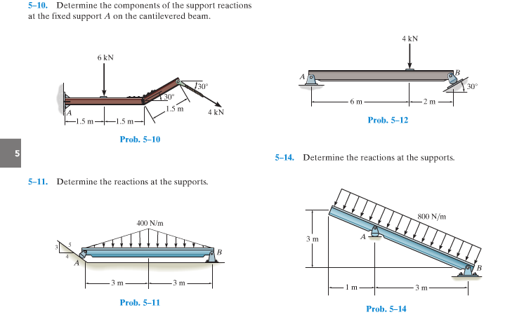
Solved Determine The Components Of The Support Reactions At Chegg Com
Transcribed image text: Draw the free-body diagram for the cantilevered beam. A is the a fixed support Draw the vectors starting at the black dots.

Shear Force And Bending Moment Diagram For Cantilever Beam With Udl Mechanical Engineering Concepts And Principles
Step 2: Make a cut along the members of interest. Here comes the most important part of solving a truss using the method of Sections. It involves making a slice through the members you wish to solve. This method of structural analysis is extremely useful when trying to solve some of the members without having to solve the entire structure using ...

How To Draw Shear Force Bending Moment Diagram Cantilever Beam Gate 2021 Examination Youtube
Soft rock slopes were anchored with traditional steel bars and new Glass Fibre Reinforced Polymer (GFRP) bars. The difference in the anchorage performance of the two kinds of anchorage elements in soft rock and expansive soil was studied by an in-situ test. The results show that cyclic load can aggravate the bond damage of the interface between grouting body and both kinds of bars used in soft ...
Iitg Ac In
Part A Draw the free-body diagram for the cantilevered beam. A is the a fixed support. Draw the vectors starting at the black dots. The location and orientation ...
1
Solved Equilibrium Of A Rigid Body Engineering Mechanics Statics And Dynamics 14th Physics Numerade

A Cantilever Beam Ab Is Subjected To Two Concentrated Load As Shown In Figure Ex 2 Determine A Reactions At Fixed Support A And B Draw The Shear Force And Bending Moment

Civil Engineering Mechanics Cantilever Beam Shear Force And Bending Moment Diagram Practice Problem Facebook
Examples On Equilibrium Problem1 Calculate The Tension T

Draw The Moment Diagram For The Cantilevered Beam Study Com
Faculty Kfupm Edu Sa

Solved Draw The Shear And Moment Diagrams For The Loaded Cantilever Beam 1 Answer Transtutors
Shear Force And Bending Moment Diagram For Cantilever

Shear Force And Bending Moment Diagram For Cantilever Beam With Uvl Mechanical Engineering Concepts And Principles

Beam Reactions And Diagrams Strength Of Materials Supplement For Power Engineering

Solved A Cantilever Beam Abc Carries A Uniformly Distributed Chegg Com
Faculty Kfupm Edu Sa
Example 2
What Are Free Body Diagrams

Unit 5 Shear Force And Bending Moment In Beams
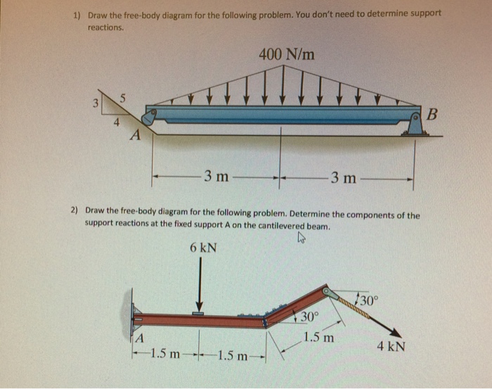
Solved Draw The Free Body Diagram For The Following Problem You Don T 1 Answer Transtutors
What Are Free Body Diagrams

Shear Force And Bending Moment Diagram For Cantilever Beam With Point Load Mechanical Engineering Concepts And Principles

Solved Part A Draw The Free Body Diagram For The Chegg Com
Solved Equilibrium Of A Rigid Body Engineering Mechanics Statics And Dynamics 14th Physics Numerade
0 Response to "37 draw the free-body diagram for the cantilevered beam. a is the a fixed support."
Post a Comment