37 minute mount 2 wiring diagram
Home · SNOW PLOW PARTS DIAGRAMS. Original Minute Mount Wiring Relay Style. FISHER & WESTERN Original Minute Mount Wiring Relay Style, last used in 2002. November 15, 2021 · Wiring Diagram. by Anna R. Higginbotham. nordyne e2eb 015ha wiring diagram - You'll need an extensive, professional, and easy to comprehend Wiring Diagram. With this sort of an illustrative manual, you will be capable of troubleshoot, prevent, and total your assignments without difficulty.
Homesteader vehicle side harness snow plow parts list fisher wiring diagram for old western the largest community plowing and ice management professionals find discussions on weather equipment tips growing your business mm2 controler ez v electrical original minute mount relay style meyer power wire battery to solenoid 36 welding cable truck ...
Minute mount 2 wiring diagram
Nov 19, 2018 — I can not find a diagram of how the wires should go to S1, S2 and S3. What was the fourth wire for? The truck is a chevy silverSil but I don't ... Aug 15, 2011 — HT Series, XtremeV & XLS Wiring. 3-Port, 2-Plug System ... applies to all Minute Mount® 2 applications. ... HT Series™ Attach/Detach Diagram ...112 pages ----- Contents (continued) Page 2 1 2 Unconfmeci and Confined Aquifers 21 213 Heterogeneity and Anisotropy 22 2 1 4 Porous Media Versus Fracture/Conduit Flow 23 215 Ground Water Fluctuations 25 216 Ground Water Divides and Other Aquifer Boundaries 26 217 Gaming and Losing Streams 28 2 2 Preparing and Using Potentiometric Maps 30 221 Plotting Equipotential Contours 30 222 Flow Nets …
Minute mount 2 wiring diagram. November 30, 2021 · Wiring Diagram. by Hadir. Pixhawk Wiring Diagram - pixhawk 2 cube wiring diagram, pixhawk 2 wiring diagram, pixhawk 2.4.8 wiring diagram, Every electrical structure is composed of various diverse components. Each part should be placed and connected with different parts in particular manner. Fisher minute mount 2 wiring harness diagram wiring diagram is a simplified agreeable pictorial representation of an electrical circuit it shows the components of the circuit as simplified shapes and the faculty and signal connections between the devices. This diagram provides information of circuit. Get Our Free Printable Rv Tool Kit Checklist ... The wiring for a 6 Kw sauna heater (#10/2), is installed from the breaker panel to the sauna control located beside the sauna door on the outside of the sauna wall. From the sauna control, the wire is run to the sauna heater. The exposed wire inside the sauna room will be encased in seal-tite flex conduit to give it mechanical and vapor protection. Fisher Minute Mount 1 Wiring Diagram : Fisher Plow... 4 Pin Starter Relay Wiring Diagram / 69 Chevy C10 ... 2 Wire Submersible Well Pump Wiring Diagram : Save... Polaris Starter Solenoid Wiring Diagram - VWVortex... Intermatic Timer Wiring Diagram : Intermatic T104 ... 2011 Ford F150 Radio Wiring Diagram - Aclk Sa L Ai...
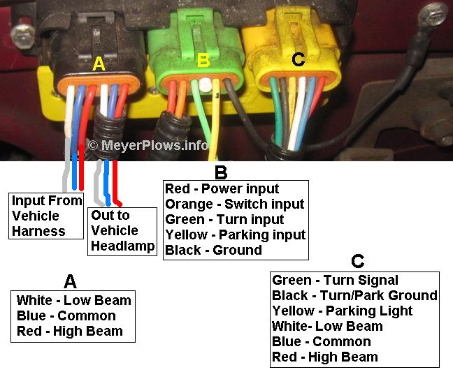
On the switch, the two larger wires are for the lights themselves. #1 is the hot wire and #2 goes to the lights. You can unplug the switch and run a jumper wire from a hot source to #2 and your brake lights should light if everything is working from the switch to the lights. To test the switch itself, use a test light or ohm meter. Technical Support Parts List & Installation Instructions Snowplows Minute Mount® 2 System & Minute Mount® System Vehicle Mounts (Peculiar Attachment Kits) Dodge : 11/18/2021: Mount Kit Ram 1500 2019-__ #77108-1 (Size: 660 KB ) 11/18/2021: Mount Kit Ram 1500 2019-__ #77108-1 ... I cut the plug in half and had to use a wire connector to attach another wire to the KC then wired it to the correct wires after cutting the factor harness. Would have been a 10 minute job but had to do the extra work so 30 minutes and she is running great. Digital timer wiring diagram. The cut sheet link is attached showing the 3 way wiring diagram. For 5 min 10 min and 15 min you just have to change the resistor value R 1. 1 Minute Timer Circuit. Electric defrost and off-cycle defrost. Digital Time Switch Eg103b E Welcome To Hager Malaysia. 1 Removing the Mechanism PU L SI M IN D DS T Spare 120V ...
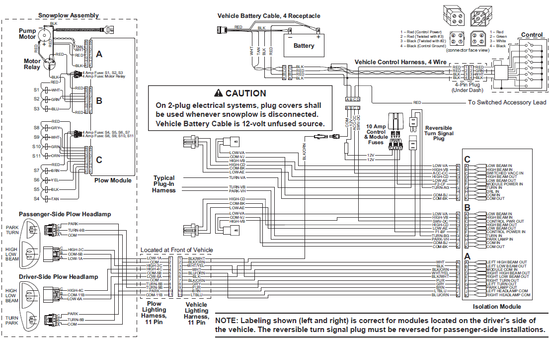
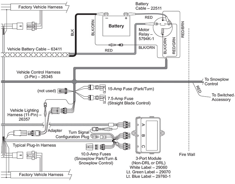
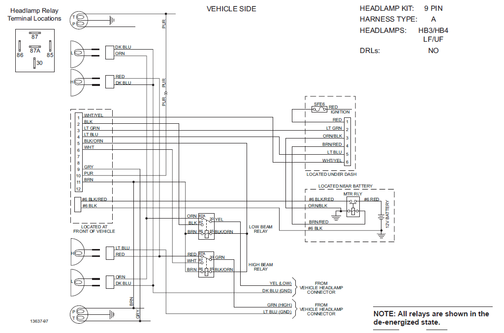
Hydraulic and Electrical Schematics . ... 2. Twist connecting pin to release tension. ... and white wires operates the high beam headlamps.72 pages HARNESS DIAGRAMS STRAIGHT BLADE STRAIGHT BLADE WIRING – 4-PORT, 3-PLUG SYSTEM Battery Factory Vehicle Harness Cable Park/Turn Lamps Battery Motor Relay Vehicle ... Craftsman Lawn Mower Carburetor Diagram. Murray Lawn Tractor Wiring Diagram. Cub Cadet Ltx 1045 Drive Belt Diagram. Husqvarna Gth2548 Drive Belt Diagram. Husqvarna Rz5424 Drive Belt Diagram. Aug 26, 2012 - (updated 01/15/2012) Find out what causes riding lawn mower belt s to break or fly off the pulleys. Get diagram of how to install your ... Headlamp Electrical Schematics - Minute Mount with Original Lights. Fisher Minute Mount 2 Plow Wiring Schematic - Wiring Diagram. Western Fisher MVP V Plow EZ V ...
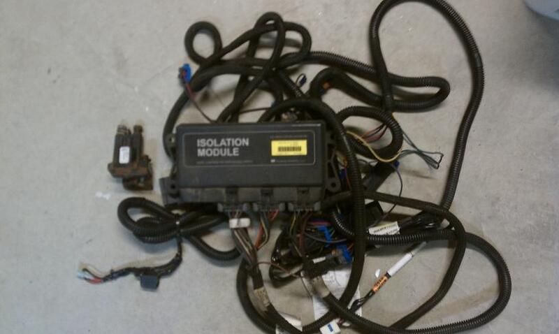
Fisher minute mount pump wire diagram the largest community for snow plowing and ice management professionals find discussions on weather equipment tips growing your business homesteader vehicle side harness plow parts list hd2 ez v electrical original wiring relay style xv2 components help 3 plug problems truck kits zequip fleet flex port 2 kit isolation module xtreme xls… Read More »

Per the wiring diagram, I'm looking at circuits A412 and A418. I can't find any detail on these, other than they are fed to Pins 15 and 16 of Connector 7, and I can tell you the color of the wires and their gauge. ... If an interior light is left ON the instrument cluster should turn it off after the 2 - 4 minute wait. ... (4x)+ Boss Audio ...
Fisher Minute Mount 2 Wiring Diagram - wiring diagram is a simplified tolerable pictorial representation of an electrical circuit. It shows the components of the circuit as simplified shapes, and the capability and signal connections between the devices. A wiring diagram usually gives assistance more or less the relative outlook and ...

A Hale Pump is a quality product: ruggedly designed, accurately machined, carefully assembled and thoroughly tested. In order to maintain the high quality of your pump, and to keep it in a ready condition, it is important to follow the instructions on care and operation.Proper use and good preventive maintenance will lengthen the life of your ... Full body midship pump s can be equipped with ...

Fisher Minute Mount 2 Wiring Diagram. Architectural wiring diagrams perform the approximate locations and interconnections of receptacles, lighting, and unshakable electrical services in a building. Printable fishera plow spreader specs fisher engineering. Diagram Fisher Plow Wiring Diagram Dodge Full Version… Continue Reading →
Hi everyone. I recently bought a 2021 F250 and put my Extreme V plow on it off my old truck. I mounted the push plates and wired everything myself. There was a small wire, that was supposed to get keyed 12 V power, that was connected to my four pin in cab controller harness. Because I have the...

wiring diagram for fisher minute mount 2 plow wiring harness diagram - Cars & Trucks question.
Original Minute Mount Wiring to Isolation ... 2. Schematics. • Schematics for the Minute Mount® System with original ... Minute Mount 2 System Headgear.56 pages
Two component phase diagram #Overview: As a first-time cultivator, I've noticed that a lot of the information regarding the well-known teks on /r/shrooms and Shroomery is spread throughout multiple different threads and found that it takes quite a bit of effort of going back and forth to properly understand some aspects of growing psilocybe ...

----- Contents (continued) Page 2 1 2 Unconfmeci and Confined Aquifers 21 213 Heterogeneity and Anisotropy 22 2 1 4 Porous Media Versus Fracture/Conduit Flow 23 215 Ground Water Fluctuations 25 216 Ground Water Divides and Other Aquifer Boundaries 26 217 Gaming and Losing Streams 28 2 2 Preparing and Using Potentiometric Maps 30 221 Plotting Equipotential Contours 30 222 Flow Nets …

Aug 15, 2011 — HT Series, XtremeV & XLS Wiring. 3-Port, 2-Plug System ... applies to all Minute Mount® 2 applications. ... HT Series™ Attach/Detach Diagram ...112 pages
Nov 19, 2018 — I can not find a diagram of how the wires should go to S1, S2 and S3. What was the fourth wire for? The truck is a chevy silverSil but I don't ...


0 Response to "37 minute mount 2 wiring diagram"
Post a Comment