38 bending moment diagram cantilever beam
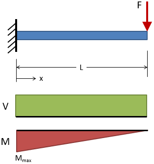
Shear Force and Bending Moment Diagram for Cantilever Beam ... Generally, in the case of cantilevers, the shear force and the bending moment will be maximum at the supports. In this case the shear force is constant throughout the length of the cantilever. Maximum S.F = +W = +12kN. Cantilever beam shear force diagram. Maximum B.M = -WL = -12 x 4 = -48kN.m. Cantilever Beam - UDL and End Bending Moment BMD = bending moment diagram E = modulus of elasticity, psi or MPa I = second moment of area, in 4 or m 4 L = span length under consideration, in or m M = maximum bending moment, lbf.in or kNm R = reaction load at bearing point, lbf or kN V = maximum shear force, lbf or kN w = load per unit length, lbf/in or kN/m
Formula For Maximum Bending Moment In Simply Supported Beam Cantilever Beam Udl And End Bending Moment. ... How To Draw Shear Force Bending Moment Diagram Simply Supported Beam Exles Ering Intro. Sf And Bm 0032 Png. Beam Deflection Calculator. Beam Design. Solved A Simply Supported Beam Deflects By 5 Mm When It Is Subjecte.
Bending moment diagram cantilever beam
[Solved] The Bending Moment Diagram of a cantilever beam ... When a moment is applied at the free end of a cantilever it will be transferred by constant magnitude to the fixed end. So, bending moment at any point will be equal to the externally applied moment. Therefore, the shape of BMD is a rectangle. ∴ Bending Moment at support (M s) = M. Take moment about the fixed end and equate it to zero. Shear Force and bending moment diagram - ExtruDesign The bending moment at the two ends of the simply supported beam and at the free end of a cantilever will be zero. Shear force and Bending moment Diagram for a Cantilever beam with a Point load at the free end Shear force and Bending moment Diagram for a Cantilever beam with a Uniformly distributed load How to Calculate Bending Moment Diagram? - SkyCiv The equation for this part of our bending moment diagram is: -M (x) = 10 (-x) M (x) = 10x Cut 2 This cut is made just before the second force along the beam. Since there are no other loads applied between the first and second cut, the bending moment equation will remain the same.
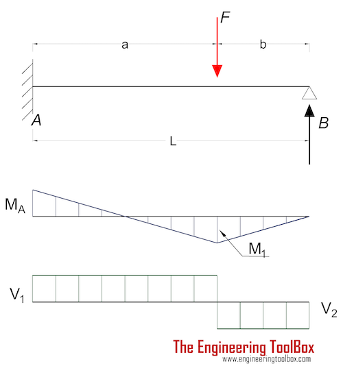
Bending moment diagram cantilever beam. Shear Force and Bending Moment diagram for cantilever beam ... In the other words, bending moment is the unbalancing moment of forces on any one side of the cross-section considered. Below diagrams are explain the shear force and bending moment diagram for Cantilever Beam. Concentrated load at the free end. Uniformly distributed load PDF Beam Design Formulas With Shear and Moment Shear and moment diagrams and formulas are excerpted from the Western Woods Use Book, 4th edition, and are provided herein as a courtesy of Western Wood Products Association. Introduction Notations Relative to "Shear and Moment Diagrams" E = modulus of elasticity, psi I = moment of inertia, in.4 L = span length of the bending member, ft. Free Online Beam Calculator for Cantilever or ... - SkyCiv Any changes made will automatically re-draw the free body diagram any simply supported or cantilever beam. The beam reaction calculator and Bending Moment Calculations will be run once the "Solve" button is hit and will automatically generate the Shear and Bending Moment Diagrams. civilmint.com › shear-force-and-bending-momentShear Force and Bending Moment Diagram for Cantilever Beam ... Case 01. Shear Force and Bending Moment Diagram of Cantilever beam when point load is applied. From the figure we have the value of load at point A and point B. So let’s draws the shear force diagram with the help of these loading. Bending moment at point A is zero. Bending moment at point B= -2*2 = 4 KN-M. Bending moment at point C= -2*4-4*2 = 12 KN-M.
Shear Force & Bending Moment diagram for Cantilever Beam ... This video shows the shear force and bending moment diagram for a cantilever beam. Cantilever is the type of beam having fixed support at one end and free at... Beam Stress & Deflection - MechaniCalc The bending moment, M, along the length of the beam can be determined from the moment diagram. The bending moment at any location along the beam can then be used to calculate the bending stress over the beam's cross section at that location. The bending moment varies over the height of the cross section according to the flexure formula below: Bending moment and shear force diagram of a cantilever beam A bending moment diagram is the graphical representation of the variation of he bending moment along the length of the beam and is abbreviated as B.M.D. We will take different cases of beams and loading for plotting S.F. D and B.M.D. Cantilever : Point Load at the End (Fig. 3.8) Cantilever Beams - Moments and Deflections M = bending moment (Nm, lb in) I = moment of Inertia (m4, mm4, in4) The maximum moment in a cantilever beam is at the fixed point and the maximum stress can be calculated by combining 1b and 1d to σmax = ymax F L / I (1e) Example - Cantilever Beam with Single Load at the End, Metric Units
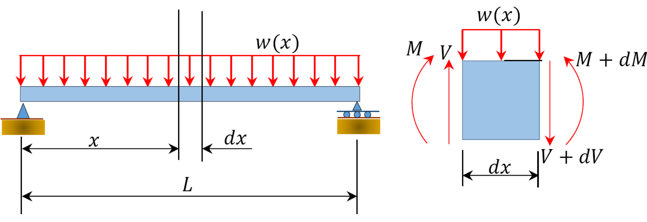
PDF Beam Diagrams and Formulas BEAM DIAGRAMS AND FORMULAS 3-219 Table 3-23 (continued) Shears, Moments and Deflections 18. CANTILEVERED BEAM- LOAD INCREASING UNIFORMLY TO FIXED END PDF 4. Bending Moment and Shear Force Diagram Construction of bending moment diagram xThe bending moment diagram is obtained by proceeding continuously along the length of beam from the left hand end and summing up the areas of shear force diagrams using proper sign convention. xThe process of obtaining the moment diagram from the shear force diagram by summation is The moment diagram for a cantilever beam subjected to ... Mar 07,2022 - The moment diagram for a cantilever beam subjected to bending moment at end of beam will bea)cubic parabolab)rectanglec)triangled)ellipticalCorrect answer is option 'B'. Can you explain this answer? | EduRev Mechanical Engineering Question is disucussed on EduRev Study Group by 3164 Mechanical Engineering Students. Cantilever Beam Calculator - calcresource Cantilever beam with point moment In this case, a moment is imposed in a single point of the beam, anywhere across the span. In practical terms, it could be a force couple, or a member in torsion, connected out of plane and perpendicular to the beam.
Beam Deflection Tables | MechaniCalc
Draw Bending Moment & Shear Force Diagrams - Cantilever Beam This video explains how to draw shear force diagram and bending moment diagram with easy steps for a cantilever beam loaded with a concentrated load. Shear f...
Given a wall-mounted cantilever beam, describe the shear ...
PDF Lecture 2 - Shear and Bending Moment and Review of Stress 3.2 - Shear Force & Bending Moment Diagrams What if we sectioned the beam and exposed internal forces and moments. This exposes the internal Normal Force Shear Force Bending Moment ! What if we performed many section at ifferent values Of x, we will be able to plot the internal forces and bending moments, N(x), V(x), M(x) as a function Of position!
![Cantilever Beam: Shear Force and Bending Moment Diagram [SFD BMD Problem 2] By Shubham Kola | Facebook](https://lookaside.fbsbx.com/lookaside/crawler/media/?media_id=257540402398666&get_thumbnail=1)
Cantilever Beam: Shear Force and Bending Moment Diagram [SFD BMD Problem 2] By Shubham Kola | Facebook
Bending Moment Diagram - BrainDuniya Bending moment diagram for the beam is drawn in figure ( c ). Drawing of beam diagrams for a cantilever with varying load Consider about a cantilever beam of length ( l ) (l) loaded with a gradually varying load from zero at free end B B to ( w ) (w) per unit length at the fixed end A A as shown in figure. SPACE DIAGRAM -

Example 420 Propped Cantilever - Structural Analysis ...
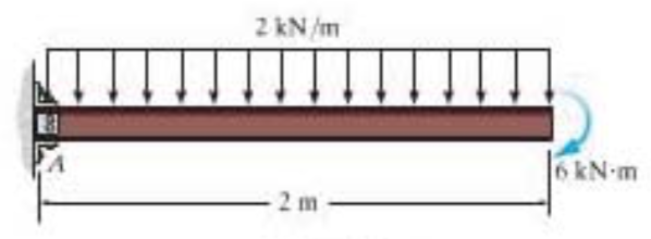
PDF Module -4 Shear Force and Bending Moment Diagrams - NCET Variation of shear force and bending moment diagrams S.N Point Load UDL UVL Shear Force Constant Linear Parabolic Bending Moment Linear parabolic Cubic WORKED EXAMPLES 1) A cantilever beam of length 2 m carries the point loads as shown in Fig. Draw the shear force and B.M. diagrams for the cantilever beam. Shear Force Diagram S.F. at D, F D
6.2 Shear/Moment Diagrams – Engineering Mechanics: Statics
Shear Force & Bending Moment Diagram of Cantilever Beam ... Shear Force & Bending Moment Diagram of Cantilever Beam Structural Mechanics Civil Engineering HindiShear Force Diagram SFD & BMD Bending Moement Diagram of ...

Draw the moment diagram for the cantilevered beam. | Study.com
PDF Shear force and bending moment of beams Beams Cantilever Beam A Built-in or encastre' support is frequently met. The effect is to fix the direction of the beam at the support. In order to do this the support must exert a "fixing" moment M and a ... The bending moment diagram is a series of straight lines between loads. The slope of
Beam Stress & Deflection | MechaniCalc
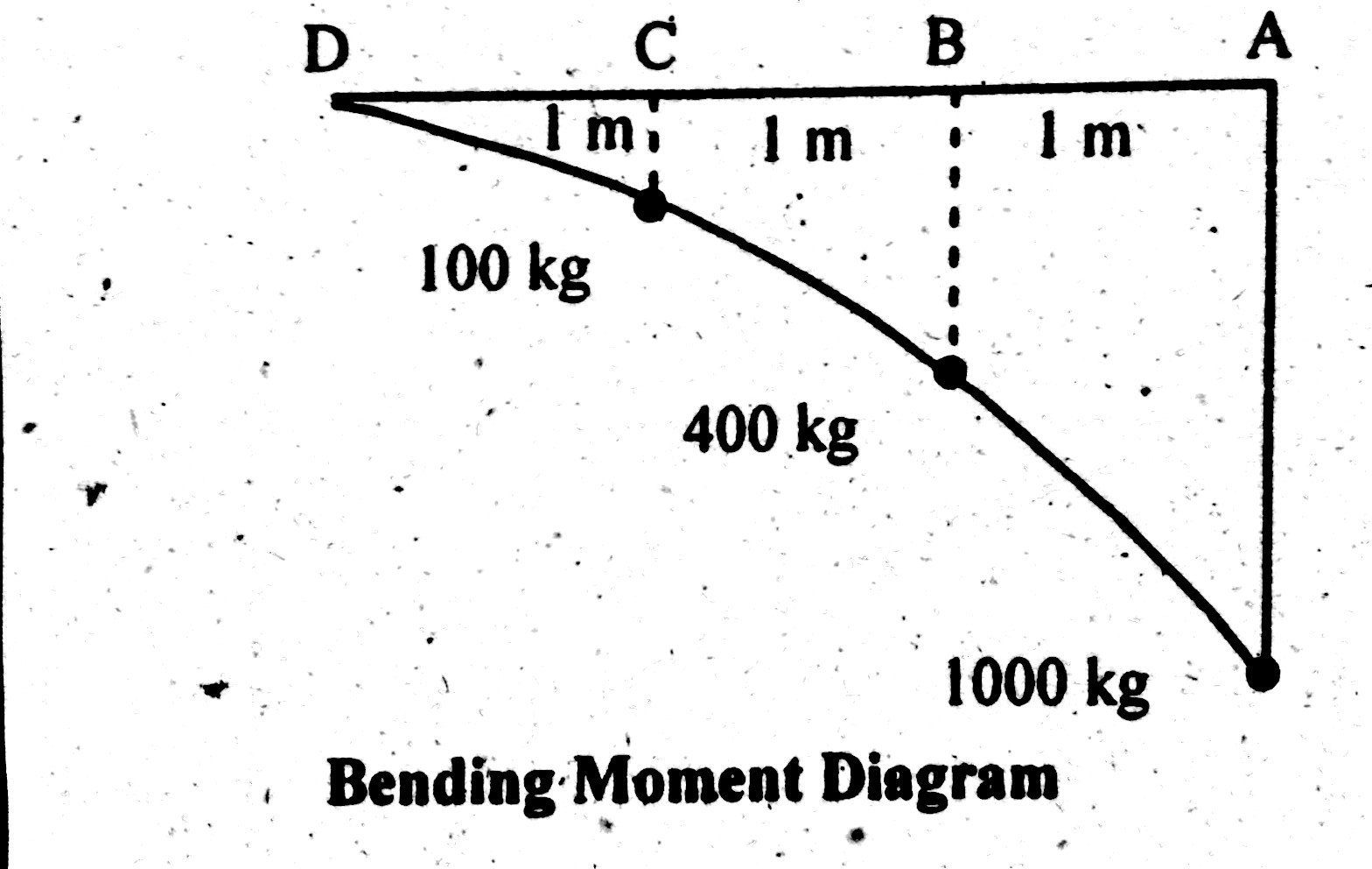
› mechanics-of-structuresShear Force & Bending Moment Diagram of Cantilever Beam ... Oct 15, 2014 · This shows shear force is maximum at fixed end and minimum at free end of cantilever beam. Shear Force Diagram. Bending Moment. Bending moment at point D = B.M (D) = 0. Bending moment at point C = B.M (C) = -(100×1) = -100 kg.m. Bending moment at point B = B.M (B) = – (100×2 +200×1) B.M (B) = -400 kg.m

Shear and moment diagram - Wikipedia
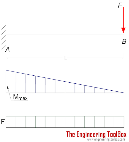
Cantilever Beam - Point Load and Bending Moment at Free End BMD = bending moment diagram E = modulus of elasticity, psi or MPa I = second moment of area, in 4 or m 4 L = span length under consideration, in or m M = maximum bending moment, lbf.in or kNm P = total concentrated load, lbf or kN R = reaction load at bearing point, lbf or kN V = maximum shear force, lbf or kN

structural engineering - Problem while solving for the moment ...
PDF Shear Force And Bending Moment Diagrams Examples may 13th, 2018 - example draw shear force and bending moment diagram of cantilever beam carrying point loads as shown in figure''free online beam calculator cloud structural software may 11th, 2018 - free online beam calculator draw the shear and moment diagrams for the beam and calculate the deflection of a shear force diagram

Solved) - Draw the shear and moment diagrams for the loaded ...
How do you calculate the bending moment of a beam ... The shape of the bending moment diagram for a cantilever beam carrying a uniformly distributed load over its length is. a straight line. a hyperbola. What is a flexural formula? Stresses caused by the bending moment are known as flexural or bending stresses. Consider a beam to be loaded as shown.

Draw the shear force and bending moment diagrams for a ...
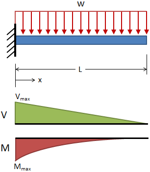
Cantilever Beam With Uniformly Distributed Load Udl Shear ... The supported end of the beam may be built into masonry or it may be a projection from a simply supported beam. a typical shearing force diagram and a typical bending moment diagram for a cantilever beam with concentrated, point loads are shown in fig. 7(b) and (c). fig. 7. fig. 8.
Chapter 4: Internal Forces in Beams and Frames” in ...
How to Calculate Bending Moment Diagram? - SkyCiv The equation for this part of our bending moment diagram is: -M (x) = 10 (-x) M (x) = 10x Cut 2 This cut is made just before the second force along the beam. Since there are no other loads applied between the first and second cut, the bending moment equation will remain the same.

Moment Diagrams Constructed by the Method of Superposition ...
Shear Force and bending moment diagram - ExtruDesign The bending moment at the two ends of the simply supported beam and at the free end of a cantilever will be zero. Shear force and Bending moment Diagram for a Cantilever beam with a Point load at the free end Shear force and Bending moment Diagram for a Cantilever beam with a Uniformly distributed load

Cantilever Beam | It's Complete Overview and important ...
[Solved] The Bending Moment Diagram of a cantilever beam ... When a moment is applied at the free end of a cantilever it will be transferred by constant magnitude to the fixed end. So, bending moment at any point will be equal to the externally applied moment. Therefore, the shape of BMD is a rectangle. ∴ Bending Moment at support (M s) = M. Take moment about the fixed end and equate it to zero.

SHEAR FORCE AND BENDING MOMENT DIAGRAM FOR CANTILEVER BEAM ...

classical mechanics - Bending moment in a cantilever beam ...

Everything You Should Know About Cantilever Beams - The ...
Beams - Fixed at One End and Supported at the Other ...
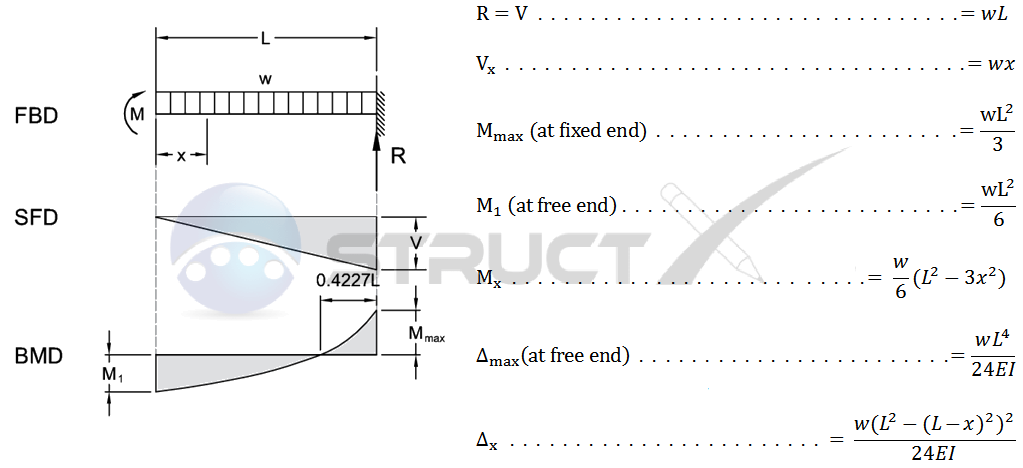
Cantilever Beam - UDL and End Bending Moment

The shear force and bending moment are zero at the free end ...

01. Draw the shear force and bending moment diagrams for the ...
What is the shear force and bending moment of a cantilever ...

Solidworks Tutorial of Shear Force and Bending Moment Diagram ...

What's the Difference Between Beam Diagrams? | Machine Design

Shear force and bending moment diagram - MechanicalStuff4u

Statics eBook: Shear and Moment Diagrams II
Cantilever Beams - Moments and Deflections
Shear Force & Bending Moment Diagram of Cantilever Beam ...

Cantilever Beam with Uniformly Distributed Load. | Download ...
T311-Propped Cantilever Beam with a Centered Load – tquigley.com
Solved] Question5 please :D | Course Hero

Civil Engineering: Shear Force and Bending Moment diagram for ...
Solved Problems) 6-4, Bending, Mechanics of Materials by R C ...
Bending Moment Diagram - BrainDuniya
![[Ex. 07] Shear Moment Diagram Cantilever Beam Distributed Load Part I](https://i.ytimg.com/vi/qMk5IVKcZQM/maxresdefault.jpg)
[Ex. 07] Shear Moment Diagram Cantilever Beam Distributed Load Part I
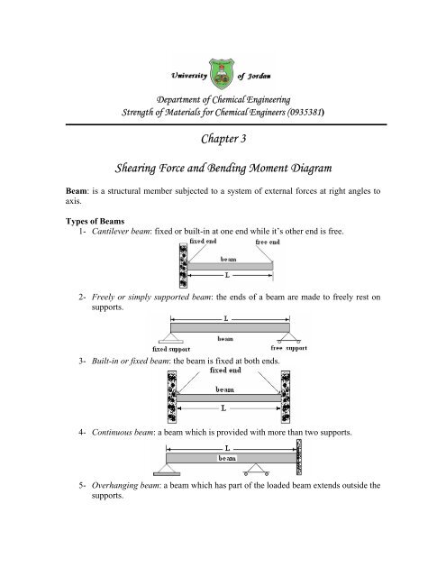
Chapter 3 Shearing Force and Bending Moment Diagram - FET
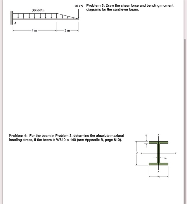
SOLVED:70KN Prcblemn 3: Draw the shear force and bending ...

Sketch the shear and bending moment diagrams for the ...
0 Response to "38 bending moment diagram cantilever beam"
Post a Comment