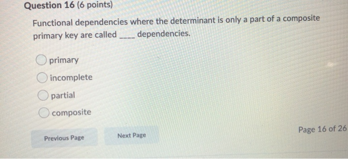
41 in an er diagram, primary keys are indicated by ____.
When ER diagrams are draw, they don't include the foreign keys in the entity types. However, the primary keys of certain entity types are composed for multiple attributes including the foreign keys. The standard way to indicated that an attribute (or set of attributes) is used as the primary key is by... ER models, also called an ER schema, are represented by ER diagrams. The primary key is indicated in the ER model by underlining the attribute. A candidate key is selected by the alternate key: all candidate keys not chosen as the primary keycandidate key: a simple or composite key that...
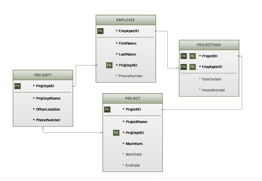
What Is an ER Diagram? An entity-relationship diagram (also known as ERD) depicts the data model of a system (or its part) using entities that represent data types and relationships that define the dependencies Entity attributes, primary and foreign keys are defined as a part of the diagram.
In an er diagram, primary keys are indicated by ____.
(T/F) In an ER diagram, primary keys are usually bolded. False (T/F) The Crow's Foot model is less implementation-oriented than the Chen model. False existence-independent entity entity can exist apart from one or more related entities (T/F) Connectivities and cardinalities are established by business rules. True In an ER diagram, primary keys are usually bolded. Ideally, a primary key is composed of several attributes. A composite key is a primary key composed of more than one attribute. All attributes are either simple or composite. All simple attributes are also single-valued. ...Some key great things about Key Attributes In Er Diagram are more talked about in the following paragraphs. Visual Counsel The most important advantage of ERD is it supplies a... Some essential benefits of In An Er Diagram Primary Keys Are Indicated By are further more reviewed in this post.
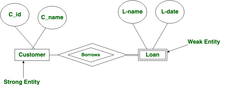
In an er diagram, primary keys are indicated by ____.. Er diagram tips. Entity relationship diagram examples. With SmartDraw, You Can Create More than 70 Different Types of An entity relationship diagram (ERD) shows the relationships of entity sets stored in a database. An entity in this context is an object, a component of data. An entity relationship model, also called an entity-relationship (ER) diagram, is a graphical representation of entities (which will become your tables) and their relationships to For example, we can know the number of employees working in a specific department by counting the number of rows. ER Diagram stands for Entity Relationship Diagram, also known as ERD is a diagram that displays the relationship of entity sets stored in a database. The member of a weak entity set called as a subordinate entity set. Primary Key is one of its attributes which helps to identify its member. The primary key is an attribute or a set of attributes that uniquely identify a specific instance of an Let's assume that for each employee in an organization there are three candidate keys: Employee ID There is no standard method for representing primary keys in ER diagrams. For this article, the...
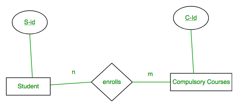
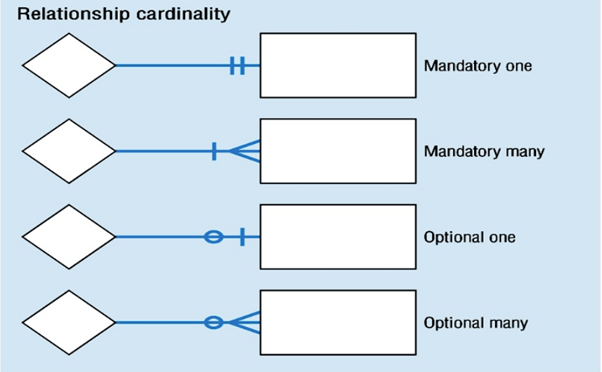
* Primary keys * Foreign keys * Multiplicity (whether a relationship between entity sets is one-to-one, one-to-many or What are the uses of an ER diagram in software engineering? Foreign keys are most often used to join two tables — from a foreign key in one table to a primary key in another table. An ER model can also be expressed in a verbal form, for example: one building may be divided into zero Diagrams created to represent attributes as well as entities and relationships may be called In a relational database a relationship between entities is implemented by storing the primary key of... In an ER diagram, primary keys are indicated by ____. Underlining. In the ERD, cardinality is indicated using the ____ notation. Min,Max. Knowing the ____ number of ... ER Diagram Representation, Let us now learn how the ER Model is represented by means of an ER diagram. Any object, for example, entities, attributes of an Name of the relationship is written inside the diamond-box. All the entities (rectangles) participating in a relationship, are connected to it by a line.
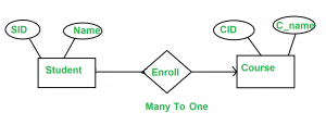
In an ER diagram, primary keys are indicated by ____. Underlining. In the ERD, cardinality is indicated using the ____ notation. Min,Max. Knowing the ____ number of entity occurrences is very helpful at the application software level. Maximum and Minimum. Making sure all ____ are identified is a very important part of a database designer’s job. A weak entity has a primary key that is partially or totallyderived from the parent entity in the relationship. ... In an ER diagram, primary keys are indicated by ____. a. bolding. c. underlining. b. italics. d. a special font. c. underlining. The ideal number of attributes used to make up a primary key is____. a. zero. c. two. b. one. d. six ... In an ER diagram, primary keys are indicated by ____. a. bolding c. underliningb. italics d. a special font. underlining. In an ER diagram, primary keys are usually bolded. false. In both the Chen and Crow's Foot models, an entity is represented with a rectangle containing the entity's name. A simple ER Diagram: In the following diagram we have two entities Student and College and their relationship. An attribute describes the property of an entity. An attribute is represented as Oval in an ER Key attribute is represented by oval same as other attributes however the text of key attribute is...
Designing a Good Database†in “Guide to Database Systems†on ...
Conceptual ER diagram symbols. Conceptual Data Models establish a broad view of what should be included in They don't have primary keys, and have no meaning in the diagram without their parent entity. Foreign keys are created any time an attribute relates to another entity in a one-to-one or...
Mapping from ER Model to Relational Model - GeeksforGeeks
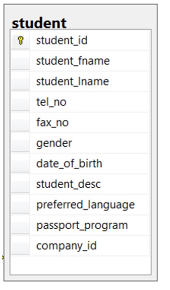
ER diagram is a conceptual model that gives the graphical representation of the logical structure of the database. ER Diagram Symbols are used to represent each Roll_no is a primary key that can identify each entity uniquely. Thus, by using student's roll number, a student can be identified uniquely.
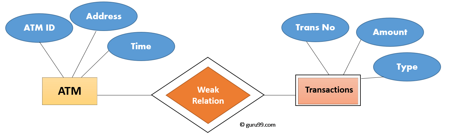
Weak Entity Set in ER diagrams - GeeksforGeeks
Ratings 100% (1) 1 out of 1 people found this document helpful. This preview shows page 10 - 13 out of 26 pages. 12. In an ER diagram, primary keys are 26. Composite primary keys are particularly useful as identifiers of composite entities, where each primary key combination is allowed only once...
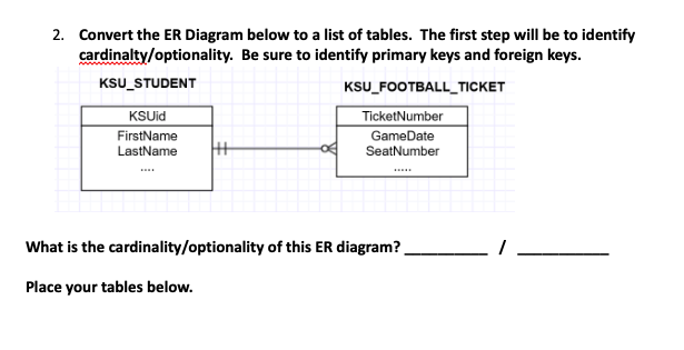
Solved 2. Convert the ER Diagram below to a list of tables ...
Learn about ER diagram symbols, how to draw ER diagrams, best practices to follow when drawing ER diagrams Rendering this information through an ER diagram would be something like this It uses a foreign key combined with its attributed to form the primary key. An entity like order item is a...
Minimization of ER Diagrams - GeeksforGeeks
This primary key is a unique value that will not be repeated in any other row of that particular relation. It is also very unlikely to change. Representing relationships in a relational schema. Once you've identified the degree and cardinality of the relationships in your ER diagram, you can start to...
ER Diagram: Entity Relationship Diagram Model | DBMS Example
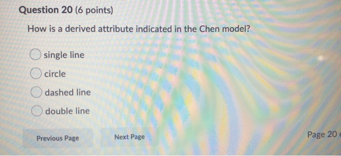
In an ER diagram, primary keys may be indicated by the letters PK and by ____. underlining italics bolding the letter case. underlining. When the PK of one entity contains the PK of a related entity, the relationship is ____. missing weak strong neutral. strong. A derived attribute ____.
![The Entity Relationship Model - Learning MySQL [Book]](https://www.oreilly.com/library/view/learning-mysql/0596008643/httpatomoreillycomsourceoreillyimages234879.png)
The Entity Relationship Model - Learning MySQL [Book]
So, with this ER Diagram tool, your ER design is no longer just a static diagram but a mirror that reflects truly the physical database structure. Also known as PK, a primary key is a special kind of entity attribute that uniquely defines a record in a database table. In other words, there must not be...

Data Modeling and Entity Relationship Diagram (ERD)
In ER diagrams, entities are usually depicted by rectangles, with the entity name at the top. Client, City and Country Entities of a Data Model. The relationship between data in one table and data in another table is called cardinality. Specifically, the cardinality indicates the number of times one entity in a...
Chapter 8 The Entity Relationship Data Model – Database ...
Entity Relationship Diagram (ER Diagram or ERD) is a pictorial or visual representation of classifying groups or entities of common interest and defining the Entity Relationship Diagram is primarily used in the following areas Primary key is derived from another entity. Represented by a single diamond.
ER Diagram: Entity Relationship Diagram Model | DBMS Example
An Entity Relationship Diagram (ERD) is a type of diagram that lets you see how different entities (e.g. people, customers, or other objects) relate to each other in an application or a database. They are created when a new system is being designed so that the development team can understand how to...

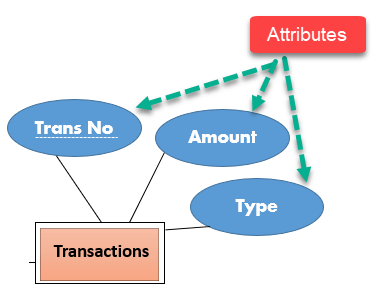
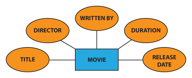
What is an attribute?
In an ER diagram, primary keys are indicated by ____. underlining. The Crow's Foot model is less implementation-oriented than the Chen model. False. Some attributes are classified as ____. Correct simple. Relationships operate only in one direction. false. The word "entity" in the ER model corresponds to a table.
Chen Notation | Vertabelo Database Modeler
The ER diagram is a way to model a database in an organized and efficient way. Dashed underlines indicate partial keys. Other Keys You May Come Across. Foreign keys are not used in E-R models, but they are used in relational databases to indicate an attribute that is the primary key of another...

Chapter 4 - Entity Relationship (ER) Modeling Compiled By: Mr ...
Facts about ER Diagram Model: ER model allows you to draw Database Design It is an easy to use graphical tool for modeling data Widely used in Primary Key is one of its attributes which In a weak entity set, it is a combination of. helps to identify its member. primary key and partial key of the strong.

Data Modeling and Entity Relationship Diagram (ERD)
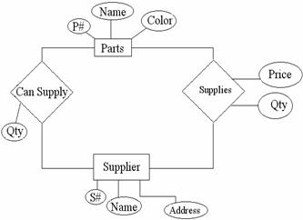
An e-r diagram efficiently shows the relationships between various entities stored in a database. Attributes are indicated by ovals in an e-r diagram. A primary key attribute is depicted by an underline in the e-r diagram. An attribute can be characterized into following types
Solved Discuss the topic. In the ER diagram below, identify ...
ER Diagrams were originally used only to represent the ER model. The ER model does not use foreign keys to represent relationships. This makes it clear which column in the child table is the foreign key to the parent table. Indicating primary key status can be done by underlining the attribute in question.
Solved Question 15 (6 points) In an ER diagram, primary keys ...
Translation of ER-diagram into Relational Schema. Dr. Sunnie S. Chung CIS430/530. Learning Objectives. Define each of the following database terms Relation Primary key Foreign key Referential integrity Field Data type Null value. Discuss the role of designing databases in the analysis and design...

Chapter 8 The Entity Relationship Data Model – Database ...
How To Represent A Foreign Key In Er Diagram – Entity Relationship Diagrams are the most effective tools to convey in the complete process. These diagrams are definitely the graphical reflection in the stream of information and information. These diagrams are most frequently used in enterprise agencies to produce information traveling simple.

Chapter 4 questions - CH4 Multiple Choice Identify the choice ...
A candidate key of an entity set is a minimal super key Customer-id is candidate key of customer account-number is candidate key of Although several candidate keys may exist, one of the candidate keys is selected to be the primary key. Database System Concepts 2.18 ©Silberschatz, Korth and Sudarshan Degree of a Relationship Set
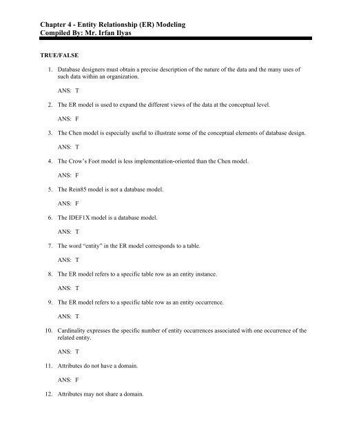
Chapter 4 - Entity Relationship (ER) Modeling Compiled By: Mr ...
In ER diagram, key attribute is represented by an oval with underlying lines. 2. Composite Attribute - An attribute composed of many other attribute is 1. Total Participation - Each entity in the entity set must participate in the relationship. If each student must enroll in a course, the participation of student...

MappingERDassignF18solutions.pdf - IS3280 Data Management ...
In an ER diagram, primary keys are indicated by ____. Underlining. In the ERD, cardinality is indicated using the ____ notation. Min,Max. Min,Max. Maximum and Minimum. Making sure all ____ are identified is a very important part of a database designer's job. Business Rules.
TYPICAL QUESTIONS & ANSWERS
October 18, 2019. October 18, 2019. · Diagram. by admin. Primary Key In Er Diagram – Entity Relationship is a higher-stage conceptual info model diagram. Entity-Relation model is founded on the notion of real-community organizations and also the relationship between the two. ER modeling allows you to examine info specifications systematically to produce a properly-created database.

Mapping the ER Model to Relational DBs
The ER process starts, like most software-engineering projects, with obtaining requirements Here is an E-R diagram for the OFFICE database. (The figure below was Fig 3.2 in an earlier edition of E Relationships, however, typically have a natural key consisting of one primary key from each entity...

Entity-Relationship Diagram Symbols and Notation | Lucidchart
...Some key great things about Key Attributes In Er Diagram are more talked about in the following paragraphs. Visual Counsel The most important advantage of ERD is it supplies a... Some essential benefits of In An Er Diagram Primary Keys Are Indicated By are further more reviewed in this post.
ER Diagram: Entity Relationship Diagram Model | DBMS Example
In an ER diagram, primary keys are usually bolded. Ideally, a primary key is composed of several attributes. A composite key is a primary key composed of more than one attribute. All attributes are either simple or composite. All simple attributes are also single-valued.

DBMS MCQ Questions With Answers Set 8
(T/F) In an ER diagram, primary keys are usually bolded. False (T/F) The Crow's Foot model is less implementation-oriented than the Chen model. False existence-independent entity entity can exist apart from one or more related entities (T/F) Connectivities and cardinalities are established by business rules. True

Mapping from ER Model to Relational Model - GeeksforGeeks

Primary and Foreign Keys

exam question 1 how to draw Entity Relationship Diagram ...
Solved Question 15 (6 points) In an ER diagram, primary keys ...
Translation of ER-diagram into Relational Schema
ER Diagram: Entity Relationship Diagram Model | DBMS Example
Chapter 8 The Entity Relationship Data Model – Database ...
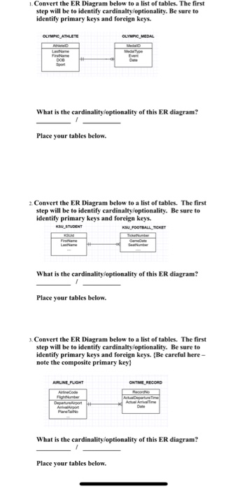
Solved I.Convert the ER Diagram below to a list of tables ...
Associative entity - Wikipedia
Solved 1. Based on the ER diagram given below, identify and ...

Entity-Relationship Diagram Symbols and Notation | Lucidchart

CIS 3365 ch4.docx - Question 1 Question 1 The ERD represents ...

MappingERDassignF18solutions.pdf - IS3280 Data Management ...
dbms objective questions
![The Entity Relationship Model - Learning MySQL [Book]](https://www.oreilly.com/library/view/learning-mysql/0596008643/httpatomoreillycomsourceoreillyimages234877.png)
The Entity Relationship Model - Learning MySQL [Book]

Question 8 An is an orderly arrangement used to logically ...
0 Response to "41 in an er diagram, primary keys are indicated by ____."
Post a Comment