41 draw the shear diagram for the compound beam which is pin connected at b.
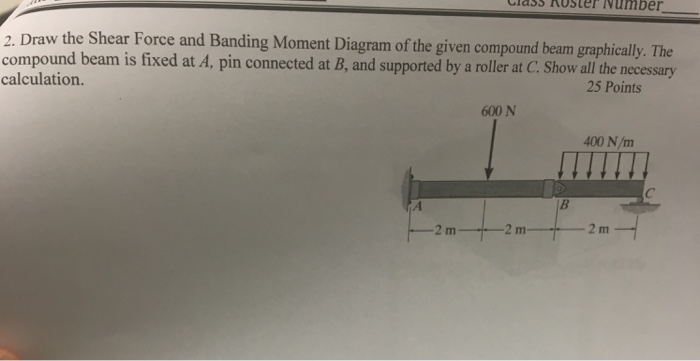
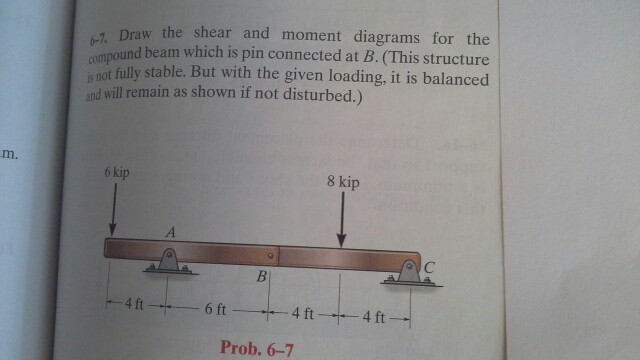
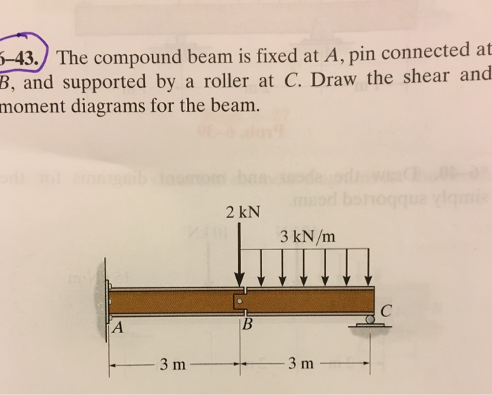
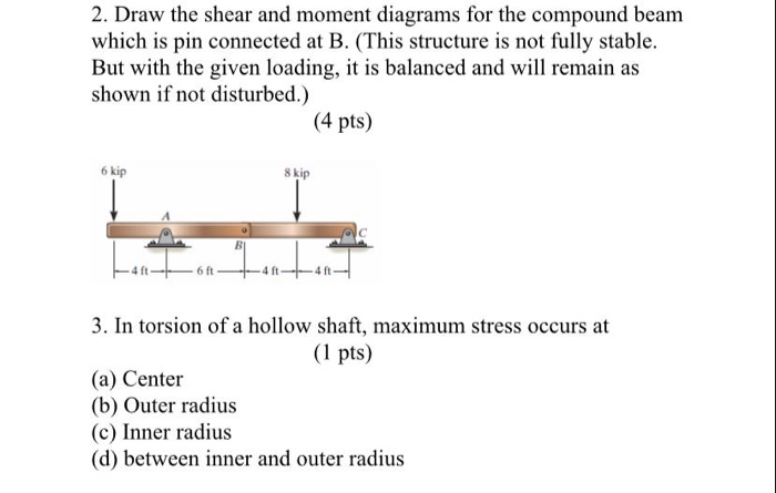
[Solved] The compound beam is fixed at A, pin connected at ... The compound beam is fixed at A, pin connected at B, and supported by a roller at C. Draw the shear and moment diagrams for the beam. The compound beam is fixed at A and supported by rockers at There are hinges (pins) at D and E. Determine the components of reaction at... Ch06 07 pure bending & transverse shear - SlideShare Draw the shear and moment diagrams for the beam. 2 m 3 m 10 kN 8 kN 15 kNиm 6-6. Draw the shear and moment diagrams for the overhang beam. A B C 4 m 2 m 8 kN/m 6-7. Draw the shear and moment diagrams for the compound beam which is pin connected at B. 4 ft 6 kip 8 kip A C B 6 ft 4 ft 4 ft 06 Solutions 46060_Part1 5/27/10 3:51 PM Page 331 5.
SOLVED:The compound beam is fixed at A, pin connected at B ... VIDEO ANSWER: in this community. Beyond that, a spring is a stretch by a distance X. And it exerts a force that is given to us. Now we have to find the wagon when the spring is a stretch from 0.1 two, m. So first o

Draw the shear diagram for the compound beam which is pin connected at b.
(Solved) - Draw the shear and moment diagrams for the ... The compound beam is fixed at A, pin connected at B, and supported by a roller at C. Draw the shear and moment diagrams for the beam. Posted one year ago View Answer Answered: , The compound beam is fixed at A, pin… | bartleby , The compound beam is fixed at A, pin connected at B, and supported by a roller at C. Draw the shear and moment diagrams for the beam. 600 N 400 N/m B check_circle Expert Answer Chapter 7 The compound beam is fix supported at A, pin connected at B and supported by a roller at C. Draw the shear and moment diagrams for the beam. 3 ft 610 C B A 6 ft 7 Solutions 44918 1/27/09 10:39 AM Page 611 © 2010 Pearson Education, Inc., Upper Saddle River, NJ.
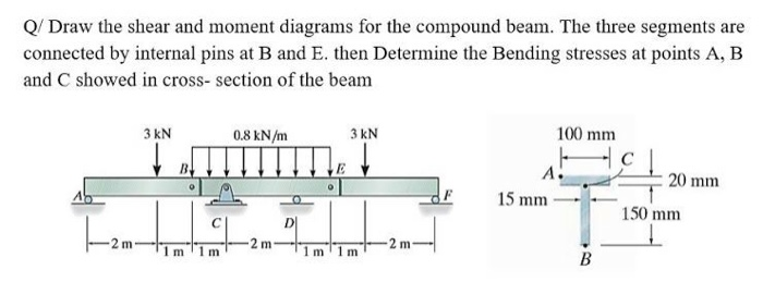
Draw the shear diagram for the compound beam which is pin connected at b.. Solved > *11-40. Draw the shear and moment diagrams for ... 11-42. Draw the shear and moment diagrams for the compound beam.... 11-43. The compound beam is fixed at A, pin connected at B, and supported by a roller at C. Draw the shear and moment diagrams... *11-44. Draw the shear and moment diagrams for the beam. 11-45. A short link at B is used to connect beams AB and BC ... 11-46. Determine ... SOLVED:The compound beam is fixed at A, pin connected at B ... There's a couple of pin joints along the beam, so it's segmented into three sections. There's ruler supports here in here, and then there's another roller at the right. So in this case we have a linearly varying distributed load over the first segment and a uniform distributed load over the other two segments. PDF Analysis of Statically Determinate Structures - UMD Analysis of Simple Diaphragm and Shear Wall Systems Problems ... pin-connected joint fixed support A B P actual beam L/2 L/2 torsional spring joint pin support torsional spring support idealized beam A B ... The compound beam is stable. It is also indeterminate to the second degree. SOLVED:The beam consists of three segments pin connected ... we have. Ah, beam that is see here is simply supported at is pinned at the left end. There's a couple of pin joints along the beam, so it's segmented into three sections. There's ruler supports here in here, and then there's another roller at the right. So in this case we have a linearly varying distributed load over the first segment and a uniform distributed load over the other two segments.
Solved The compound beam is fixed at A, pin connected at B ... The compound beam is fixed at A, pin connected at B, and supported by a roller at C. Draw the shear and moment diagrams for the beam. Question: The compound beam is fixed at A, pin connected at B, and supported by a roller at C. Draw the shear and moment diagrams for the beam. PDF 6-1. Draw the shear and moment diagrams for the shaft.The ... Draw the shear and moment diagrams for the beam. 2 m 3 m 10 kN 8 kN 15 kN m 6-6. Draw the shear and moment diagrams for the overhang beam. A B C 4 m 2 m 8 kN/m 6-7. Draw the shear and moment diagrams for the compound beam which is pin connected at B. 4 ft 6 kip 8 kip A C B 6 ft 4 ft 4 ft 06 Solutions 46060_Part1 5/27/10 3:51 PM Page 331 The compound beam is fixed at A, pin connected at B, and ... The compound beam is fixed at A, pin connected at B, and supported by a roller at C. Draw the shear and moment diagrams for the beam. Step-by-Step Report Solution Verified Solution Scan the QR Code To Continue Browsing on Your mobile Device. Answered: *11-44. Draw the shear and moment… | bartleby Engineering Mechanical Engineering Q&A Library *11-44. Draw the shear and moment diagrams for the compound beam which is pin connected at B. (This structure is not fully stable. But with the given loading, it is balanced and will remain as shown if not disturbed.) 30 KN 40 KN -1m
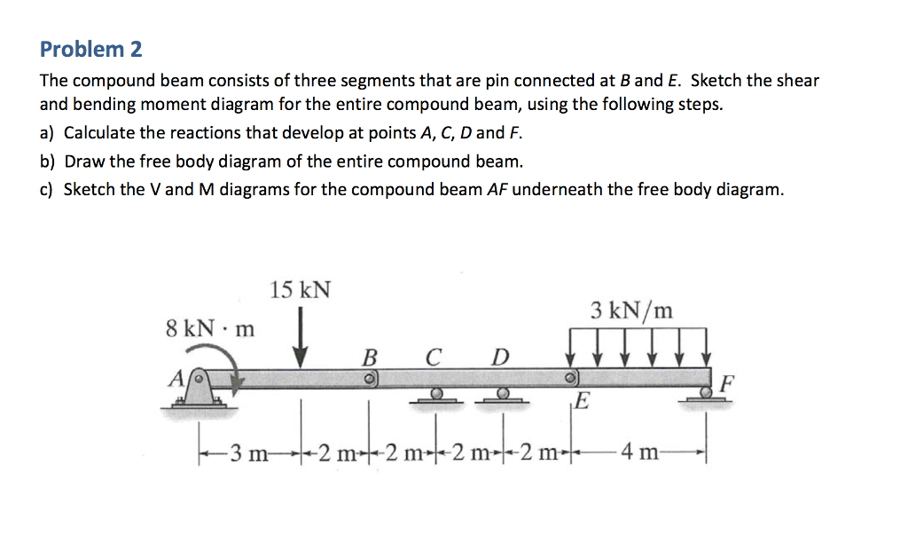
Draw the shear and moment diagrams for the compound beam ... Take-Home: Problem 6.7, Page 279 Draw the shear and moment diagrams for the compound beam which is pin connected at B . Draw the shear and moment diagrams for the pipe. The end screw is subjected to a horizontal force of 5 kN. Hint: The reactions at the pin C must be replaced by an equivalent loading at point B on the axis of the pipe. Compound Beam Shear and Moment Diagram - YouTube Drawing shear force and bending moment diagram for a compound beam#Engineering #civil_engineering #structuralengineering #structural_engineering#هندسة_مدنية#... PDF Chapter 4 Shear and Moment In Beams - ncyu.edu.tw 4.3 Shear- Moment Equations and Shear-Moment Diagrams The determination of the internal force system acting at a given section of a beam : draw a free-body diagram that expose these forces and then compute the forces using equilibrium equations. The goal of the beam analysis -determine the shear force V and (Solved) - The beam consists of three segments pin ... The compound beam consists of three segments that are pin connected at B and E. Sketch the shear and bending moment diagram for the entire compound beam, using the following steps. a) Calculate the reactions that develop at points A, C, D and F. b)...
329 6–1. Draw the shear and moment diagrams for ...
The Compound Beam Is Fixed At A 33+ Pages Explanation in ... The compound beam is fixed at A pin connected at B and supported by a roller at C. Draw the shear and moment diagrams for the beam. The compound beam in the attachment is fixed at A pin connected at B and supported by a roller at C. 600N 400 Nm -2m. Draw the shear and moment diagrams for the beam.

Solved) - *7-56, Draw the shear and moment diagrams for the ...
Answered: 10 kN/m |2m 2m 2m 6m 6m 2. A compound… | bartleby 10 kN/m B. JE E 6m 2m 2m 2m 6m 2. A compound beam is pin connected at E and Fas shown above. a. Determine the shearand moment equations of the given figure. b. Draw the shear diagram. Determine the value of X when shearis zero. C. d. Draw the moment diagram.

Draw the shear and moment diagrams for the compound beam ...
The compound beam is fix supported at A, pin connected The compound beam is fix supported at A, pin connected at B and supported by a roller at C. Draw the shear and moment diagrams for thebeam. Students also viewed these Civil Engineering questions Draw the shear and moment diagrams for beamCD.

Statics 7.61 - Draw the shear and moment diagrams for the beam.
Solved > 11-43. The compound beam is fixed at A,:2017973 ... The compound beam is fixed at A,:2017973 ... | ScholarOn. Question : 11-43. The compound beam fixed at A, pin connected at : 2017973. 11-43. The compound beam is fixed at A, pin connected at B, and supported by a roller at C. Draw the shear and moment diagrams for the beam.
329 6–1. Draw the shear and moment diagrams for the shaft ...
Solved Draw the shear diagram for the compound beam which ... Transcribed image text: Draw the shear diagram for the compound beam which is pin connected at B. Click on "add vertical line" to add discontinuity lines. Then click on "add segment" button to add Draw the moment diagram for the compound beam which is pin connected at B. Click on "add vertical line" to add discontinuity lines.

7-81. The beam consists of three segments pin connected at B ...
Chapter 7 The compound beam is fix supported at A, pin connected at B and supported by a roller at C. Draw the shear and moment diagrams for the beam. 3 ft 610 C B A 6 ft 7 Solutions 44918 1/27/09 10:39 AM Page 611 © 2010 Pearson Education, Inc., Upper Saddle River, NJ.

Get Answer) - For the pin-connected frame shown, sketch a ...
Answered: , The compound beam is fixed at A, pin… | bartleby , The compound beam is fixed at A, pin connected at B, and supported by a roller at C. Draw the shear and moment diagrams for the beam. 600 N 400 N/m B check_circle Expert Answer

The compound beam is fixed at A, pin connected at B, and ...
(Solved) - Draw the shear and moment diagrams for the ... The compound beam is fixed at A, pin connected at B, and supported by a roller at C. Draw the shear and moment diagrams for the beam. Posted one year ago View Answer
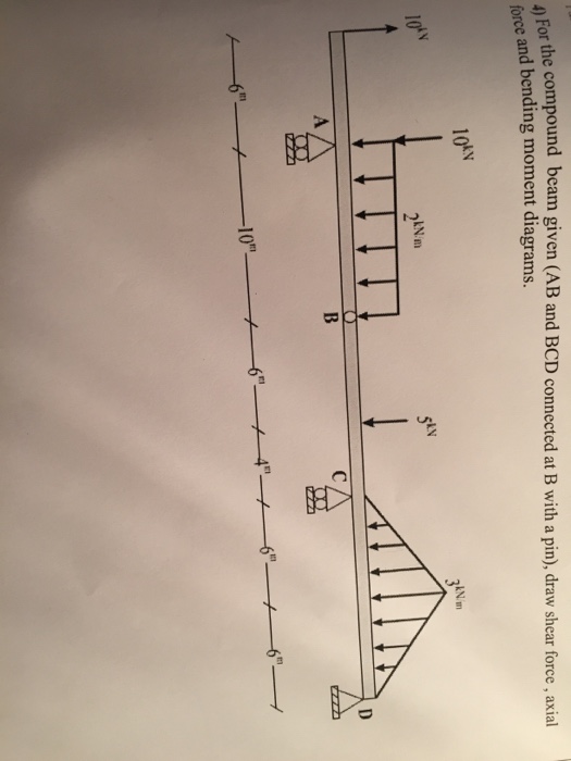
Solved) - For the compound beam given (AB and BCD connected ...

The compound beam is fixed at A, pin connected at B, and ...
Solved) - Draw the Shear Force and Banding Moment Diagram of ...
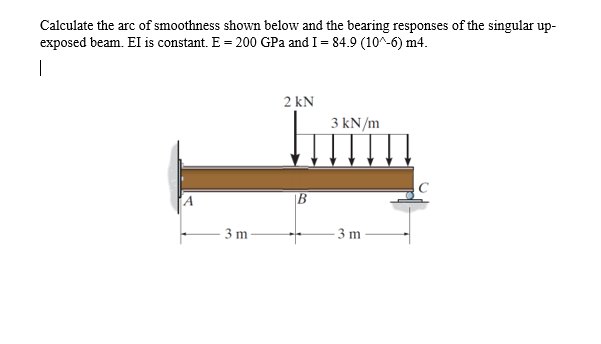
Discussion | Calculate the arc of smoothness shown below and ...
SOLVED:Draw the shear and moment diagrams for the compound ...
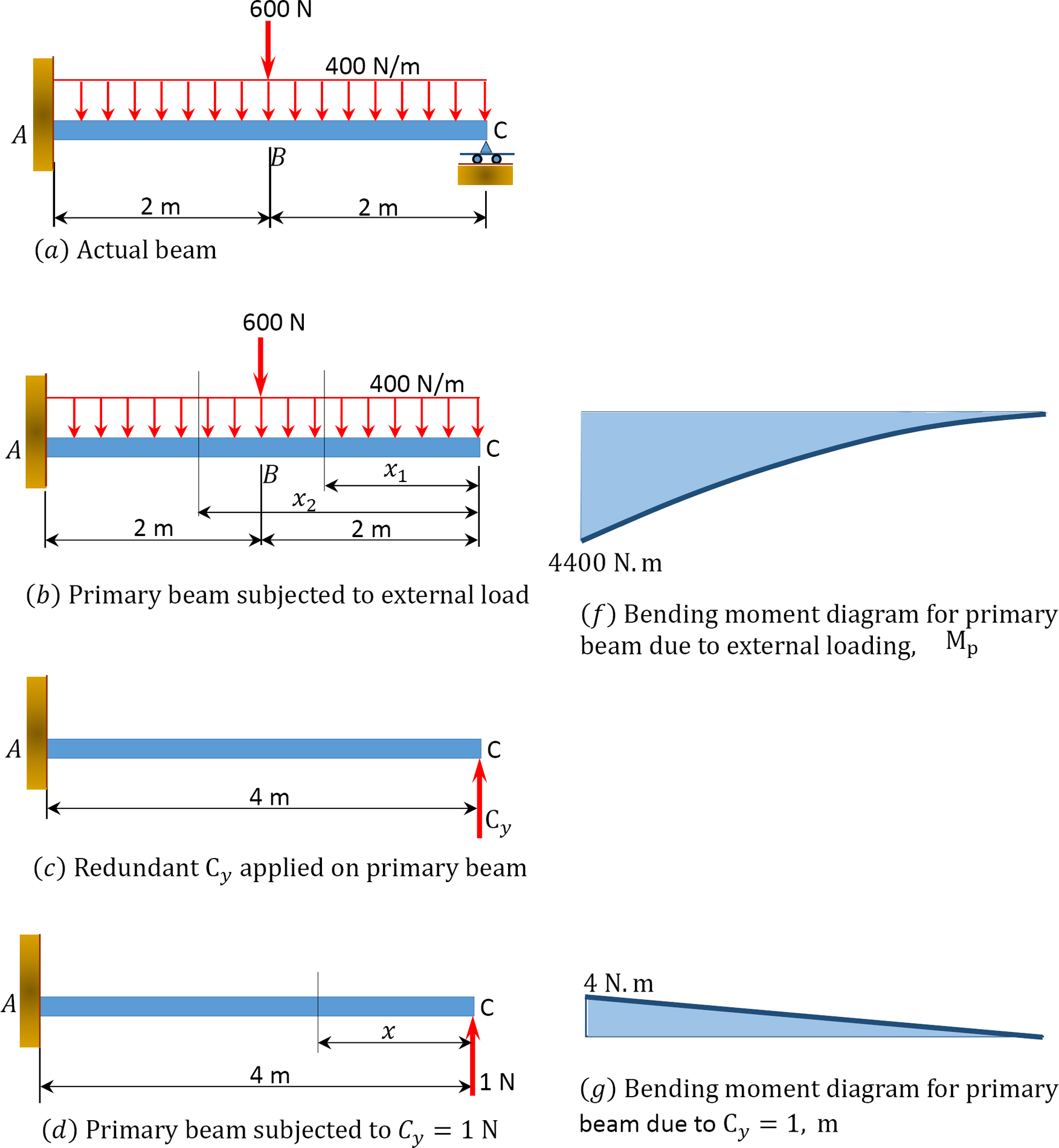
1.10: Force Method of Analysis of Indeterminate Structures ...
329 6–1. Draw the shear and moment diagrams for the shaft ...
Answered: the compound beam in the attachnent is… | bartleby
1.9: Influence Lines for Statically Determinate Structures ...
![Solved] The compound beam is fix supported at A, pin ...](https://www.solutioninn.com/images3/50-E-C-S(2041).PNG)
Solved] The compound beam is fix supported at A, pin ...

Complete the shear moment diagram The industrial robot is ...
329 6–1. Draw the shear and moment diagrams for the shaft ...

Solved) - Part A Draw the moment diagram for the compound ...
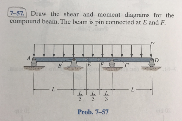
Solved 7-57. Draw the shear and moment diagrams for the ...
Solved The compound beam consists of three segments that are ...
Mechanics of Materials Chapter 4 Shear and Moment In Beams

The compound beam is fixed at A, pin connected at B, and ...
329 6–1. Draw the shear and moment diagrams for the shaft ...

Solved) - The beam consists of three segments pin connected ...

4. Draw the shear and moment diagrams for the compound beam ...

329 5–51. The compound beam is pin-supported at C and ...
Solved Draw the shear and moment diagrams for the compound ...

Draw the shear and moment diagrams for the compound beam ...
Can you draw the shear force and bending moment diagrams of ...
Solved Q Draw the shear and moment diagrams for the compound ...
Solved The compound beam is fixed at A, pin connected at B ...

The compound beam is fixed at A, pin connected at B, and ...

The compound beam is fixed at A, pin connected at B, and ...
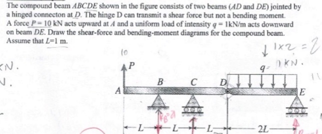
Solved) - The compound beam ABCDE shown in the figure ...

complete the shear moment diagram 400 N/m 200 N/m A B х 3 m ...
Solved 2. Draw the shear and moment diagrams for the | Chegg.com

Beam Reactions and Diagrams – Strength of Materials ...

Extra Examples. - ppt video online download
0 Response to "41 draw the shear diagram for the compound beam which is pin connected at b."
Post a Comment