41 5 wire door lock diagram
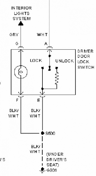
PDF INSTALLATION GUIDE OWNER'S GUIDE - Bulldog Security system. Make sure to mark which wire is lock and unlock. "Type B" Door Lock Test (Most Imports, some newer Fords) Probe both door lock wires going to the door lock switch these wires are usually located in the driver's kick panel. Attach one end of your test light to +12V using the vehicle's door lock controls activate PDF TOYOTA ELECTRICAL WIRING DIAGRAM - Autoshop 101 Wiring Diagrams 1. Understanding Diagrams Page U-1 Lighting Systems 1. Headlights Page L-1 2. Turnsignals & Hazard Page L-2 3. Stop Lights Page L-3 4. Automatic Light Turn-off Page L-4 5. Daytime Running Lights Page L-5 Accessories Systems 1. Rear Window Defogger Page A-1 2. Power Windows Page A-2 3. Power Mirrors Page A-3 4. Door Locks Page A ...
Simple 5 wire switch and door lock actuator kit - YouTube Here is an easy 5 wire setup for anyone to use in any vehicle without the use of any relays. Here is an easy 5 wire setup for anyone to use in any vehicle without the use of any relays.

5 wire door lock diagram
Help with door lock actuator wiring. - Security Center ... if you are doing a conversion from non power to power locks use the 5 wire to control the other locks. green lock, blue unlock. wire up the relays like your diagram and run it to the blue and green wire on the actuator. the actuator on the passenger door cut off the white brown and black wire and on the driver door ground the black wire and tie in the white and brown wire on the blue and green on the alarm module going to the relays so when you unlock the driver door the passenger door will ... GM Full-Size Trucks 1988-1998 Wiring Diagrams Repair Guide These GM wiring diagrams provide schematics for vehicle model years 1988 through 1998. Access our free Wiring Diagrams Repair Guide for GM Full-Size Trucks 1988-1998 through AutoZone Rewards. These diagrams include: Fig. 1: Index of Wiring Diagrams. Fig. 2: Sample Diagram: How to Read and Interpret Wiring Diagrams. Fig. 3: Wiring Diagram Symbols. PDF SAMPLE WIRING DIAGRAMS - SDC Security powering a lock, the minimum inductive load (lock) power wire guage shall be determined using the sdc wire guage chart or another voltage drop estimation tool. all wiring (single or multi- conductor) shall be color coded without splices. a minimum of two spare conductors is recommended. 6. voltage may not be specified on these wire diagrams. verify
5 wire door lock diagram. Aiphone Wiring Diagram Aiphone Wiring Diagram. Aiphone LEM-1 Manual Online: Wiring Diagrams. • LEM-1 system LEM-1 1 E + - 5 5 5 5 MOUNTING • LEM-1 6 6 OPERATIONS Calling sub On LEM-1, depress. AiPhone Intercom Wiring Diagram Recent Attractive AiPhone Lef Series Wiring Diagram Inspiration was upload at December 9, at pm by, and This. Door Locks - 5 Wire Alternating 12 Volts Positive (Type C ... Door Locks - 5 Wire Alternating 12 Volts Positive (Type C) Relay Wiring Diagram. The switch, when moved in either direction, applies both power and ground directly to motor legs without the use of any relays. Except, at the switch in this case, both motor legs rest at ground . Therefore it is only necessary to change the polarity of one motor leg to lock or unlock the vehicle. Door Locks - 5 Wire Alternating 12 Volts Positive (Type C ... Door Locks - 5 Wire Alternating 12 Volts Positive (Type C) Relay Wiring Diagram. How to Wire Automotive SPDT Relays. Door Locks - 5 Wire Alternating 12 Volts Positive (Type C). The switch, when moved in either direction, applies both power and ground directly to motor legs without the use of any relays. Except, at the switch in this case, both motor legs rest at ground . PDF CHRYSLER 3-5 WIRE DOOR LOCKS AL - Bulldog Security Title: CHRYSLER 3-5 WIRE DOOR LOCKS AL Author: Administrator Created Date: 8/11/2004 11:24:02 AM
BMW GM3 Wiring Description for E39 5-series Does you BMW E39 5-series or E53 X5 have door lock problem from the key fob and the central locking button? Do the interior lights not turn on when you open the door? You need my GM3 Repair Service. BMW GM3 Wiring Description for E39 5-series These are taken from the E39 wiring diagram. Multiple Wire Power Door Lock Systems, Add Auto Lock/Unlock 5 Wire Alternating 12 Volts Positive Door Locks Relay Diagram (Type C) Like the 4 wire configuration, the switch, when moved in either direction, applies both power and ground directly to motor legs without the use of any relays. Except, at the switch in this case, both motor legs rest at ground . Tech-Tip-1041.pdf Standard "5-Wire" With 451 Relay Pack ... Multiplexed Door Lock Wiring Diagram. ... Because multiplexed door locks are becoming the standard in today's ...21 pages PDF INSTALLATION MANUAL - Magnadyne Master Door Lock Switch X +12 Volts Input X Splice Splice Cut the Existing Lock Wire To Door Lock To Slave Door Motor Lock switch es Cut the Existing 3 Pin Plug Unlock Wire To Alarm 5-WIRE ALTERNATING DOOR LOCK 30 86 87a 85 87 to Alarm 30 86 87a 85 87 Red +12V Switch Green Wire Blue Wire POSITIVE TRIGGER DOOR LOCK SYSTEM (+) Lock Out To Door Lock (+) Unlock Out Control Relays Blue Wire: Connect to Unlock Green Wire: Connect to Lock
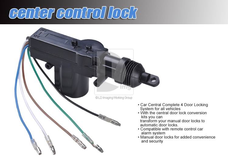
Car Central-Locking System Schematic Circuit Diagram There are 5-wire motors and 2-wire motors. The 5-wire version is used indoors that have a key-lock. There are 2 connections for the motor itself and 3 connections for the sensor part (an 'open' and a 'close' contact). These sensors determine whether the door is to be unlocked or locked. If there is no key lock in the door, these sensors ... PDF User Guide and Installation Manual Keyless Entry System ... will need to mount an actuator (GT series) in the drivers door to control your locks. Wiring diagram comes with actuator (GT series) 1. Install the fuse on the red wire then connect the BROWN/BLUE, and RED wires to a constant 12 volts. 2. From the keyless entry unit connect the ORANGE/BLUE, ORANGE/GREEN, and BLACK wires to metal ground. 3. Maglock Wiring Diagram - schematron.org The following common wiring diagrams are available: Standalone with access control and Magnetic Lock · Wireless Multi-Technology Reader - GCK> Magnetic Lock Setup Guide Diagram from the manual that shows where to connect wires. Larger diagram In this example, the manual labeled the blue wire leaving the 6-pin connector as the negative ... wiring diagram for door lock switch | Mercedes-Benz Forum When the switch is closed, the green/white wire sends a signal to terminal 6 of the PSE, either from Green/red, or ground (brown). The PSE either sends vacuum or pressure to the door lock actuator. The green/red gets power from F4f11, so fuse 11 in the rear fuse box. Other wires at the switch are only for lighting.
5 Wire Door Lock Actuator Wiring Diagram Wire Center Best Of ...
PDF installation guide nately on lock and unlock, make sure that it is not a Type C direct-wire system. Here is a test: Cut the wire that pulses (+)12 volt on lock, and then operate the switch to unlock. If all doors unlock, the vehicle uses type A system. If you lose all door lock operation in both directions, you are operating the mas-ter switch in a Type C system.

Central Locking Relay Configuration Diagrams | Manualzz
5 Wire Door Lock Diagram : Door Lock Wiring Diagram. 5 ... 5 Wire Door Lock Diagram : Door Lock Wiring Diagram. Door Lock Actuator Wiring Diagram,Remote Central Locking Wiring Diagram,Central Locking Wiring Diagram Manual,How To Install Central Locking In A Car,Door Lock Relay Location,Central Locking Wiring Diagram,Power Door Lock Relay Wiring,5 Wire Door Lock Diagram.

How-to-guides - Relay applications
2002-2003 Dodge Ram Vehicle Wiring Chart and Diagram NOTE #2: the (-) Negative PARKING LIGHTS on this vehicle will require a (-)Negative thru a 330 or 1400 Ohm Resistor and an extra Relay part #775, to connect, See DIAGRAM NOTE #3; the Door Locking System is a 1-Wire, to LOCK requires a (-)Negative thru a 820 Ohm Resistor and to UNLOCK requires a (-)Negative thru a 330 Ohm Resistor, some units ...
Door Locks : Custom Car Stereo - Complete Car Audio Building ...
PDF Chevrolet S-10 Blazer 1983-2004 POWER DOOR LOCK (5-wire reverse polarity) LT. BLUE Harness Coming Into Vehicle From Driver's Door Or Harness In Driver's Kick Panel POWER DOOR UNLOCK (5-wire reverse polarity) BLACK/WHITE Harness Coming Into Vehicle From Driver's Door Or Harness In Driver's Kick Panel PARKING LIGHTS (+) BROWN At Light Switch Or Driver's Kick Panel
Features Item Type: Alarm Systems & Security Weight: 150g ...
CHRYSLER 3/5 Wire Door Locking System - BulldogSecurity ... Use this Diagram IF your Unit DOES NOT HAVE. On-Board Door Lock Relays. To 12 volts. 30 amp constant. Requires (2) fused at 30. #775 Relays.1 page

Help with understanding power door lock diagram - Honda-Tech ...
2004-2005 Dodge Ram Vehicle Wiring Chart and Diagram When connecting to an ALARM SYSTEM, use all 4 DOOR TRIGGER wires and DIODE ISOLATE. to connect, See DIAGRAM NOTE #6: the PCM (Powertrain Control Module) is located on the PASSENGER SIDE firewall, the DIESEL tach wire is a GRAY/BLACK at the ECM (Electronic Control Module) on the lower drivers side of the engine, 60 pin plug, pin 24.
Gatekeeper Instructions v4 h4.2
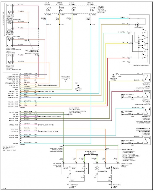
PDF SYSTEM WIRING DIAGRAMS - pswired.com 1995 System Wiring Diagrams Chevrolet - Tahoe AIR CONDITIONING A/C Circuit. Heater Circuit ANTI-LOCK BRAKES. Anti-lock Brake Circuits COMPUTER DATA LINES. Data Link Connector Circuit ... POWER DOOR LOCKS. Door Lock Circuit, 2 Door. Door Lock Circuit, 4 Door. Keyless Entry Circuit, 2 Door. Keyless Entry Circuit, 4 Door POWER MIRRORS. Power ...
need window wiring diagram for a 1973 | El Camino Central Forum
5 Wire Door Lock Actuator Wiring Diagram - autocardesign 5 Wire Door Lock Actuator Wiring Diagram. Wiring Diagram March 26, 2019 07:27. 5 Wire Door Lock Actuator Wiring Diagram Actuator Wiring Circuit Manual E Book. 5 Wire Door Lock Actuator Wiring Diagram - wiring diagram is a simplified pleasing pictorial representation of an electrical circuit. It shows the components of the circuit as simplified shapes, and the power and signal associates in the company of the devices.
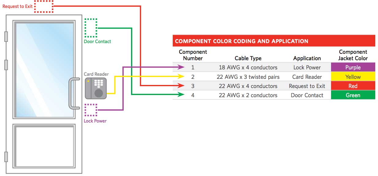
Access Control Cables and Wiring Diagram | Kisi
Power Door Locks & Wiring Diagram - YouTube Power Door Locks & Wiring DiagramAmazon Printed Bookshttps:// Kindle Editionhttp:// ...

Bulldog Security Diagrams
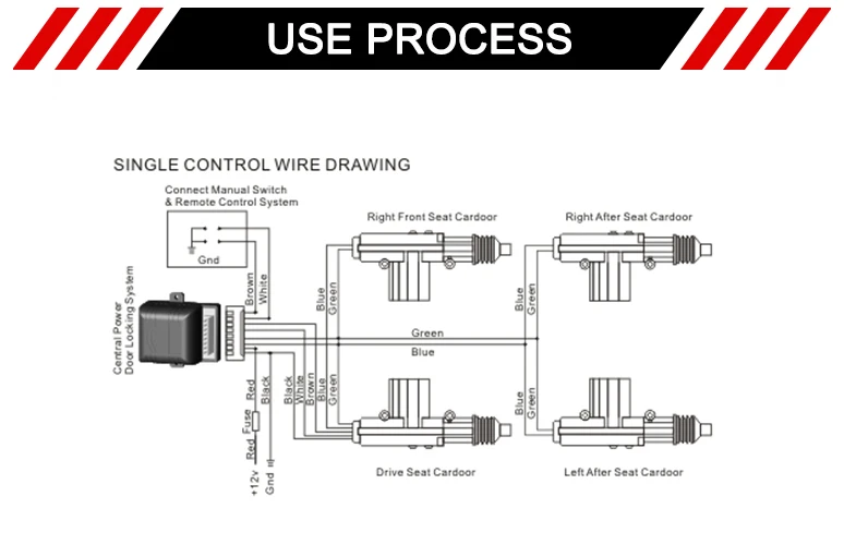
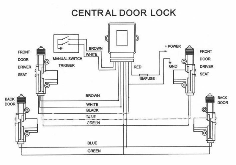
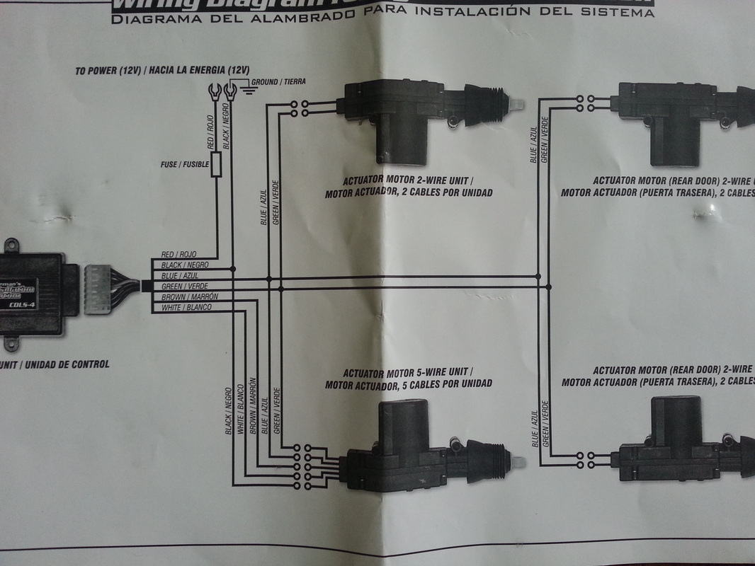
PDF Wiring Diagrams 8 Central Locking System 11. Repeat steps 1-10 for each door. WIRING 1. Run all the wires to the location of the door lock module. Be sure to mount the module in a dry place (under the dash). 2. Connect the 5 wires from the actuator to the wire harness in accordance with the same color. 3. Connect the separate black wire to a chassis ground (body metal). 4.
Door Lock Wiring - Chevy HHR Network
PDF Fitting/Installation Guide - UNIVERSAL NOTE: To help determine your door lock type, refer to the Door Lock Types by Manufacturer chart (See below) or In most cases we provide you with the Central lock wiring colour's diagram for your car (Normally a separat sheet is enclosed). If the year of your vehicle is listed as having two or more types of door lock systems, you must test for

Automotive Power Accessories and Charging Systems
PDF L - WIRING DIAGRAMS Article Text (p. 13) 2000 Mazda MX-5 ... 2000 System Wiring Diagrams Mazda - MX-5 Miata AIR CONDITIONING Heater Circuit. SYSTEM WIRING DIAGRAMS Article Text (p. 2) 2000 Mazda MX-5 Miata For Yorba Linda Miata ... Power Door Lock Circuit POWER MIRRORS. SYSTEM WIRING DIAGRAMS Article Text (p. 22) 2000 Mazda MX-5 Miata For Yorba Linda Miata

uxcell Car 5 Wire Power Door Lock Actuator for Central Locking System DC 12V
5 Wire Door Lock Actuator Wiring Diagram Wire Center Best ... Dec 27, 2020 - 5 Wire Door Lock Actuator Wiring Diagram Wire Center Best Of Power
2006 E350 - Help bypass / delete power door lock switch ...
PDF SAMPLE WIRING DIAGRAMS - SDC Security powering a lock, the minimum inductive load (lock) power wire guage shall be determined using the sdc wire guage chart or another voltage drop estimation tool. all wiring (single or multi- conductor) shall be color coded without splices. a minimum of two spare conductors is recommended. 6. voltage may not be specified on these wire diagrams. verify
Power door lock wiring diagram - Ford F150 Forum - Community ...
GM Full-Size Trucks 1988-1998 Wiring Diagrams Repair Guide These GM wiring diagrams provide schematics for vehicle model years 1988 through 1998. Access our free Wiring Diagrams Repair Guide for GM Full-Size Trucks 1988-1998 through AutoZone Rewards. These diagrams include: Fig. 1: Index of Wiring Diagrams. Fig. 2: Sample Diagram: How to Read and Interpret Wiring Diagrams. Fig. 3: Wiring Diagram Symbols.
Multiple Wire Power Door Lock Systems, Add Auto Lock/Unlock
Help with door lock actuator wiring. - Security Center ... if you are doing a conversion from non power to power locks use the 5 wire to control the other locks. green lock, blue unlock. wire up the relays like your diagram and run it to the blue and green wire on the actuator. the actuator on the passenger door cut off the white brown and black wire and on the driver door ground the black wire and tie in the white and brown wire on the blue and green on the alarm module going to the relays so when you unlock the driver door the passenger door will ...
CENTRAL LOCKING SYSTEM INSTALLATION MANUAL ACTUATORS ...
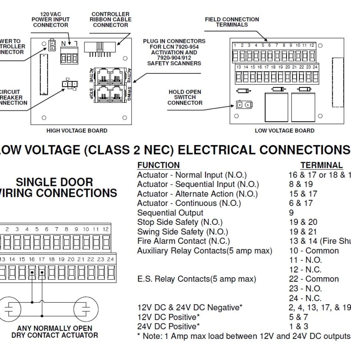
How to Coordinate Automatic Doors With Locking Devices ...

Universal car alarm system and remote control central door ...
Mazda CX-5 Service & Repair Manual - Liftgate Opener System ...
Best price auto central door locking system door lock actuator ...
Universal Door Lock Actuator Motor w /Keyless Entry 5 Wire 12V Car Truck Alarm

Dc12V 2-Wire Mini Embedded Electric Lock Glass Door Security Access Control System
Power door locks - Wikipedia
Multiple Wire Power Door Lock Systems, Add Auto Lock/Unlock
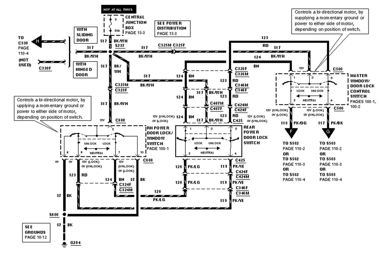
2003 E350 Power Locks Not Working | Ford Automobiles
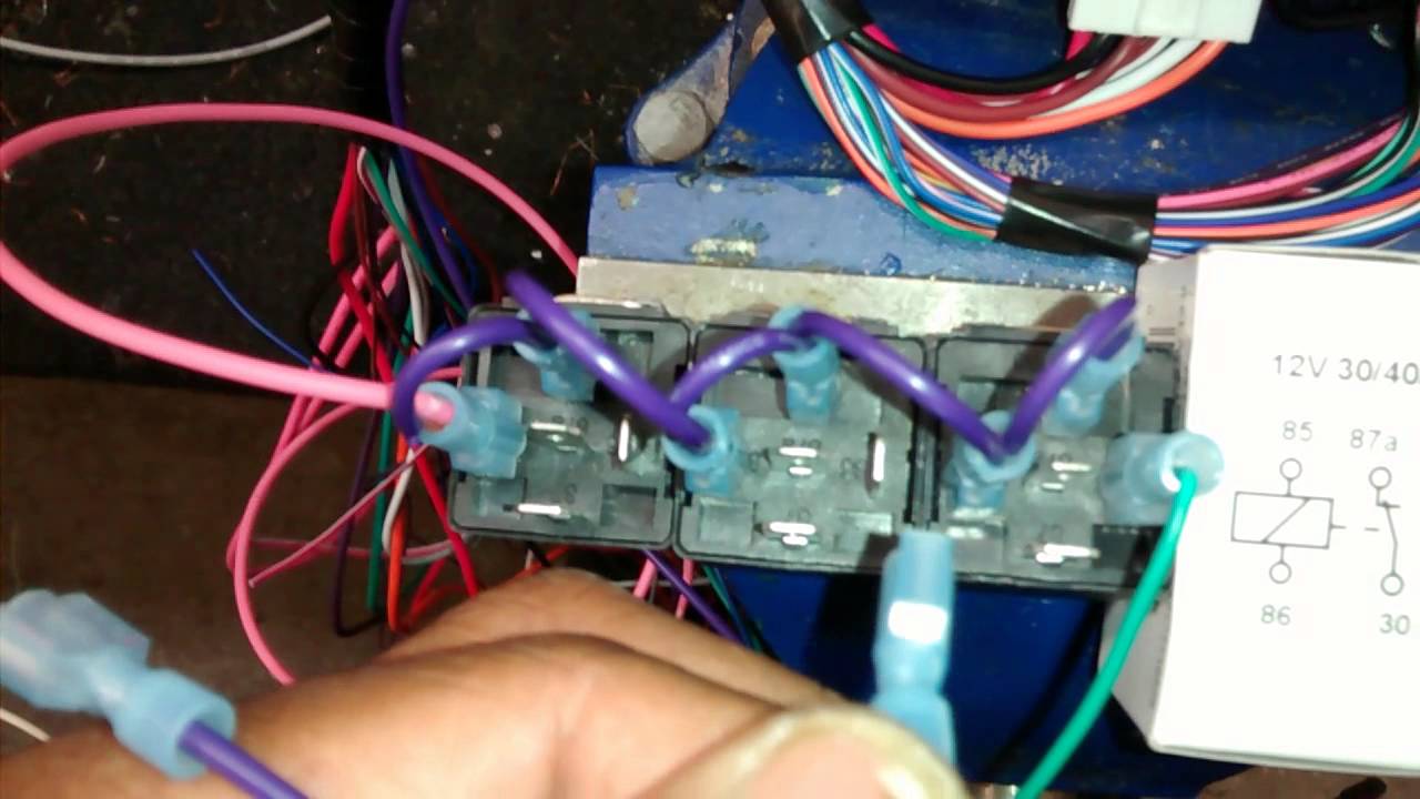
How To Wire Up A 5 wire Relay For Positive Door Locks Actuators Invert Converter
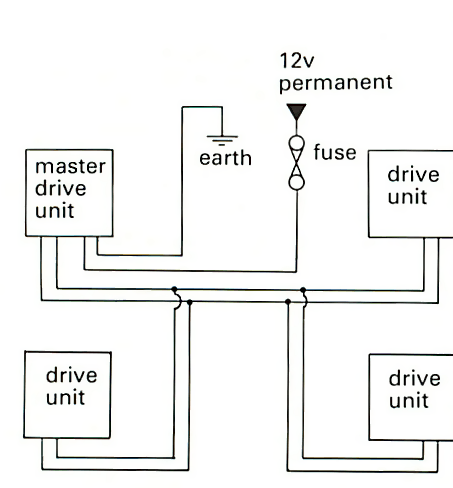
Installing central locking | How a Car Works
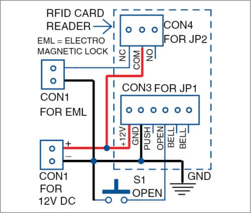
Basic Installation Of Access Control System | Full ...
Electric door lock question. | Toyota Tacoma Forum

HOW POWER LOCK DOORS WORK FROM WIRING DIAGRAM AND KEYLESS REMOTE ENTRY part 2
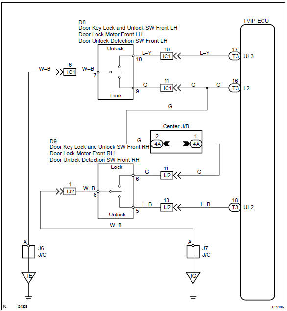
Toyota Corolla Repair Manual: Circuit description - Door key ...
Car Alarm System - Timothy Boger's Engineering Blog
Positive Pulse Door Locks for Car Alarm Installation
Standards and Procedures Installation of Access Control ...

How to Wire Relay Power Door Lock - YouTube
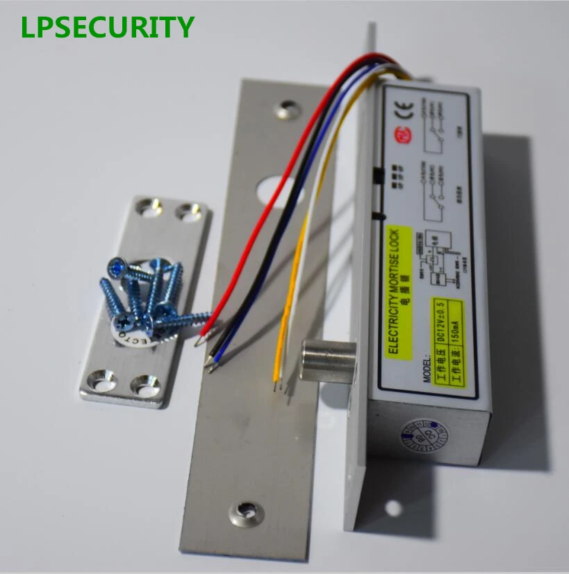
Fail secure DC12V Deadbolt Electric Drop Bolt Plug Narrow ...

X AUTOHAUX Universal Car Remote Central Kit Door Lock Keyless ...
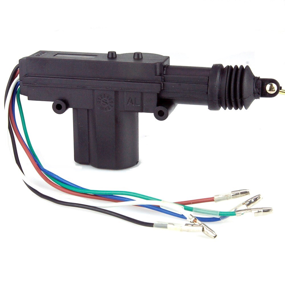
Door Lock Actuator 5 Wire
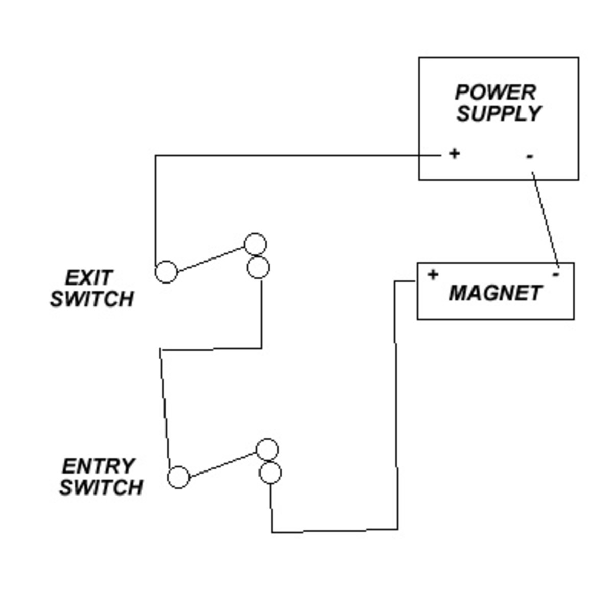
Basic Magnetic Door Lock System - HubPages

How to replace the door lock relay on Honda CRV 2005 - Motor ...
0 Response to "41 5 wire door lock diagram"
Post a Comment