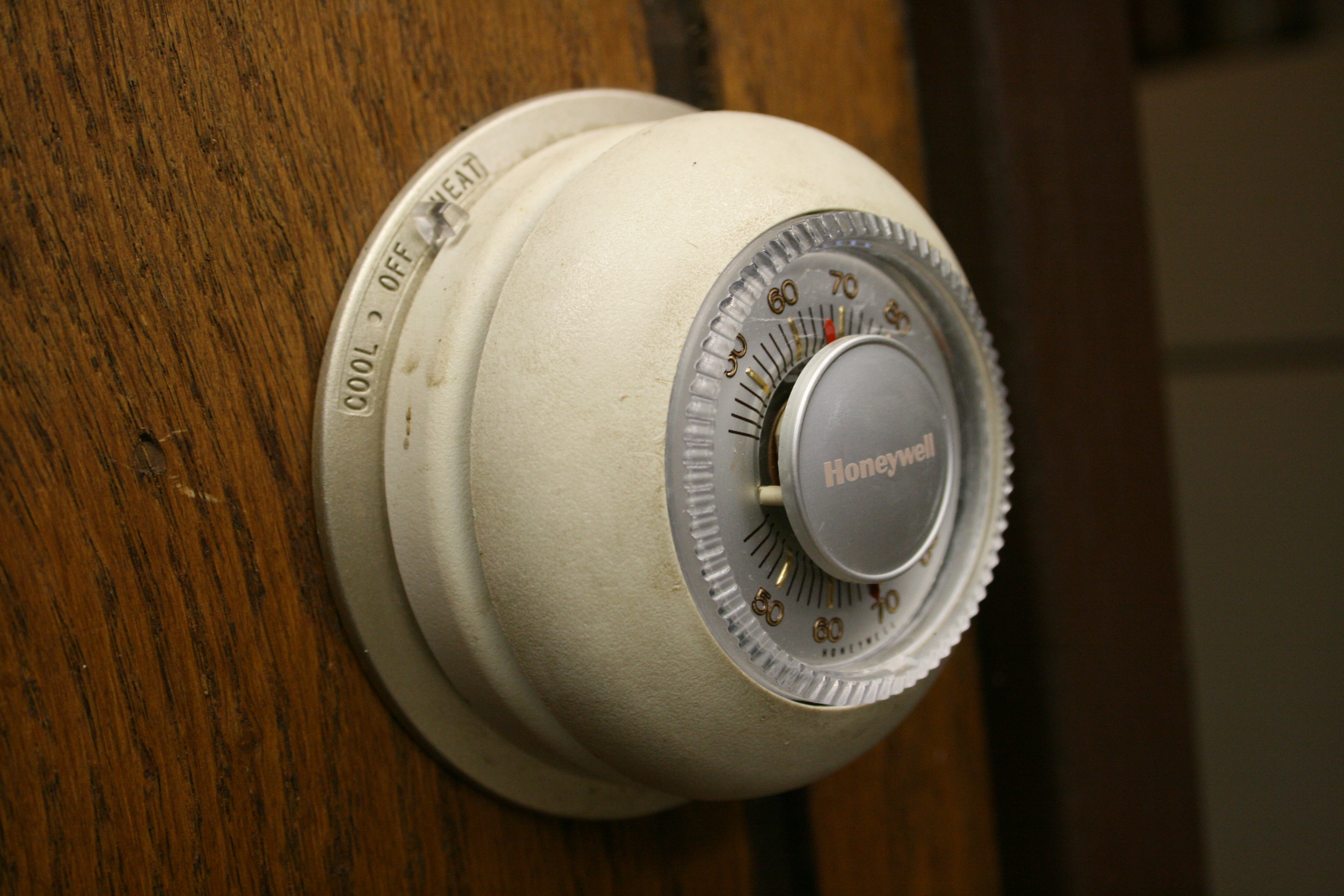
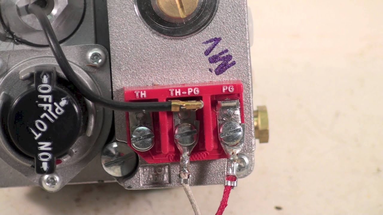
38 millivolt thermostat wiring diagram
This one covers how the gas valve on the millivolt system is wired.This video is part of the heating and cooling series of training videos made to accompany ... a thermostat is designed to stop and start loads in a system to maintain a specific temperature: ... field wiring is installed by _____ a. assembly line personnel b. installation technicians ... a pictoral or component arrangement diagram shows_____ a. the components in a circuit by circuit arrangement
If the former is the case it could probably be wired slightly differently to provide 24VAC over the thermostat wiring to charge/power the Nest. If the latter is the case I believe the thermostat terminals would provide the necessary 24VAC to charge/power the Nest as would be the case in a "traditional" (non-millivolt) setup. If the Taco SR506 ...

Millivolt thermostat wiring diagram
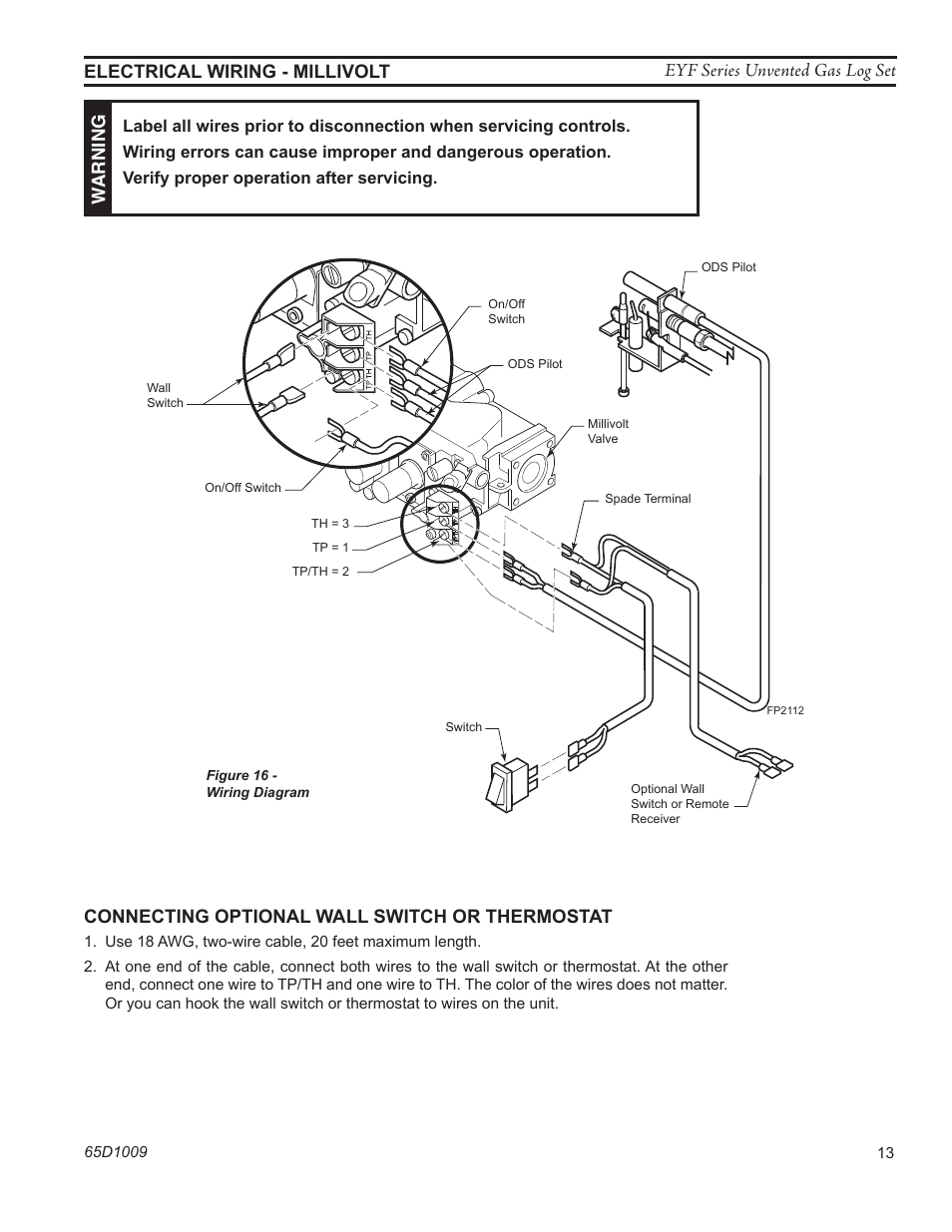
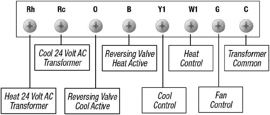
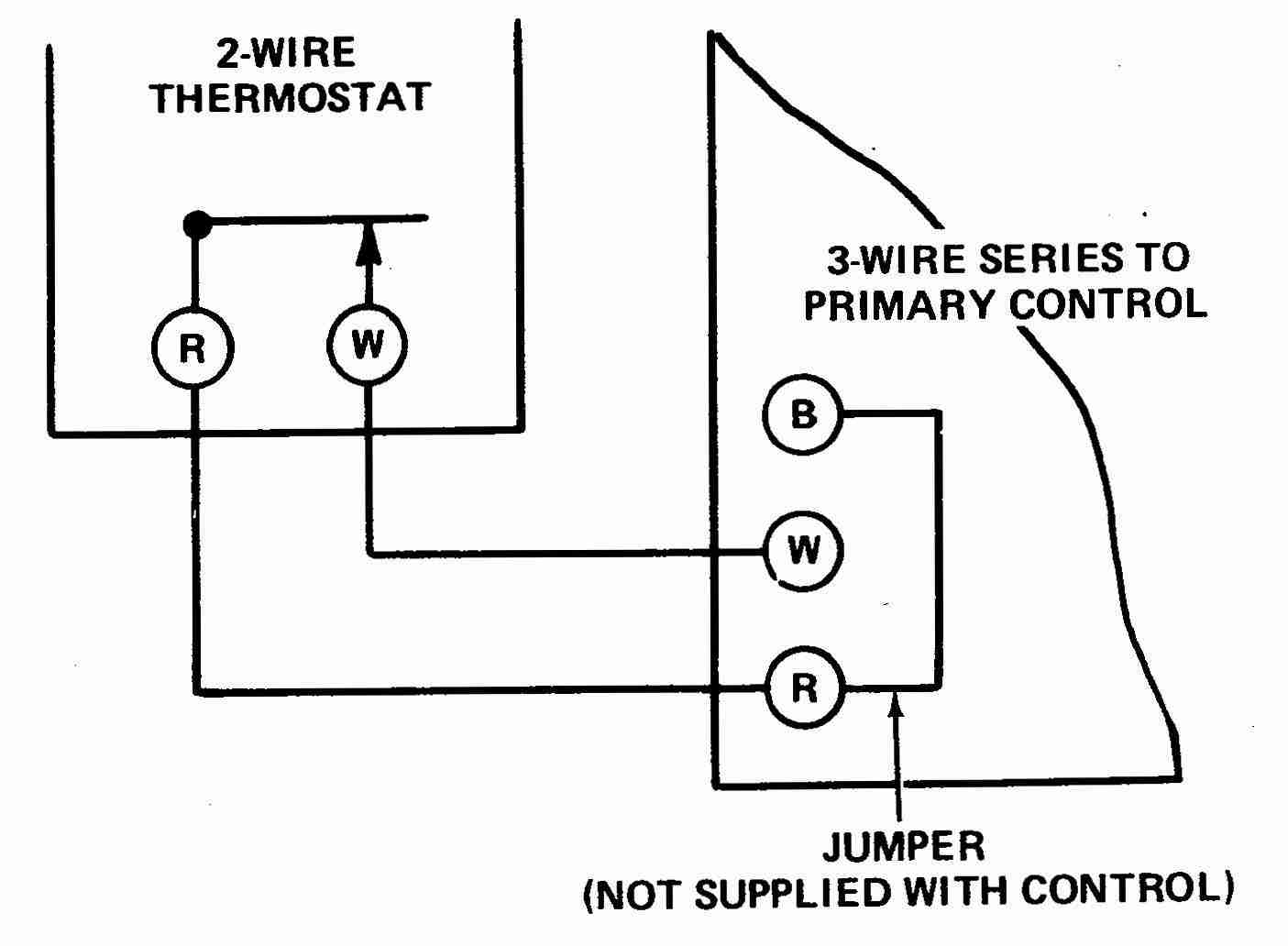
Electrical (110V and millivolt) components and wearable parts such as blowers, gas valves, thermal switch, switches, wiring, remote controls, ignitor, gasketing, and pilot assembly are covered and NAPOLEON will provide replacement parts free of charge during the first year of the limited warranty. With a few tools you can easily wire a millivolt thermostat to your heating, ventilating and air-conditioning system. Advertisement Video of the Day Step 1 Turn off the electricity to your heating unit, such as a furnace or boiler. Step 2 Connect one thermostat wire to one screw terminal on your millivolt thermostat's wall plate. ... Figure 2. Typical wiring diagram for heat only, 3-wire, single transformer systems TRANSFORMER Heating System Fan Relay Y RC JUMPER WIRE B O For 2-wire Heat only, attach to RH and W NOTE Y RH 24 VAC 120 VAC Hot Neutral TRANSFORMER THERMOSTAT SYSTEM G W Figure 3. Typical wiring diagram for cool only, 3-wire, single transformer systems Cooling ...
Millivolt thermostat wiring diagram. Millivolt Valve Wiring Diagram. By | November 13, 2021. 0 Comment. 0 item s 00 menu home products thermocouples thermopiles pilots ignitors flame sensors ignition modules cooking commerical residential heating water heater parts pool dryer regulators robertshaw 700 720 series two stage gas valves wiring diagrams diagram manualzz 4 5 recommended spare honeywell millivolt valve frymaster sm60 ... Connecting a Nest thermostat to an incompatible system, such as a millivolt, proprietary or high voltage system, won’t deliver the power needed to charge your thermostat’s battery and can damage your Nest thermostat. 4. Check your thermostat’s wiring. Symptoms caused by wiring issues usually occur when you're first installing your thermostat. Millivolt thermostat Wiring Diagram Download. millivolt thermostat wiring diagram - Just What's Wiring Diagram? A wiring diagram is a kind of schematic which uses abstract photographic signs to show all the affiliations of parts in a system. Electrical wiring representations are made up of two points: icons that represent the components in the circuit, and… WIRING DIAGRAM NOTES: (Important, please read all notes before connecting wires) • If the information provided in the following wiring diagrams does not clearly represent or match your system, please refer to the “TECHNICAL ASSISTANCE” section of this manual, and contact us before removing any of your existing thermostat wiring.
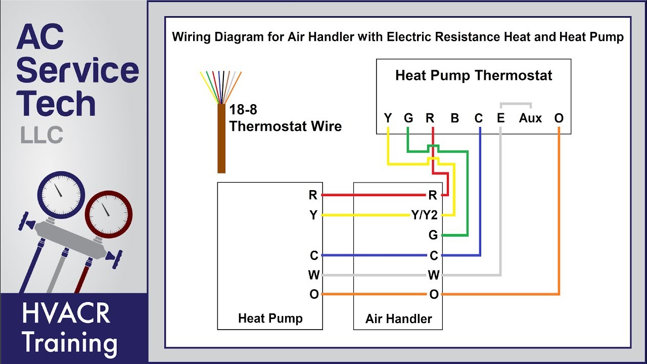
I am kindly seeking assistance/confirmation with connecting a thermostat to my gas fireplace: Napoleon Direct Vent Gas Fireplace (Model: B36NTR) with a millivolt operating system and a blower is also connected to the fireplace) Currently it is connected to a light switch via 4 conductor wire per the following: Yellow/Green wires are intertwined ... A Guide to the Different Types of Millivolt Valve Remote Controls. ... the easiest way to determine your fireplace's remote compatibility is by finding the Wiring Diagram in your fireplace Installation & Operation manual. For a standard millivolt valve, it should look something like this: ... They include the Timer, Thermostat, and simple On ... Millivolt Link NEW THERMOSTAT OPERATION Thermostat on Subbase. After power is turned on, use the system switch to select ... Typical wiring diagram heat only, 3-wire zone valve systems 6 MV B O Y G W RC THERMOSTAT Hot 24 VAC 120 VAC Neutral TRANSFORMER SYSTEM Zone Valve 6 4 5 1 2 RH www.white-rodgers.com. 8 TROUBLESHOOTING Thermostat Wiring Diagrams for Heat Pumps - Heat Pump Thermostat Wire Diagrams. Heat pumps are different than air conditioners because a heat pump uses the process of refrigeration to heat and cool.While an air conditioner uses the process of refrigeration to only cool, the central air conditioner will usually be paired with a gas furnace, an electric furnace, or some other method of heating.
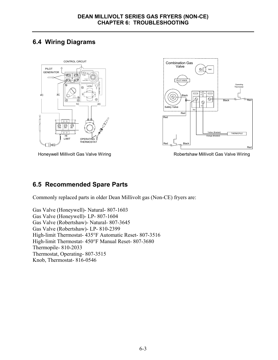
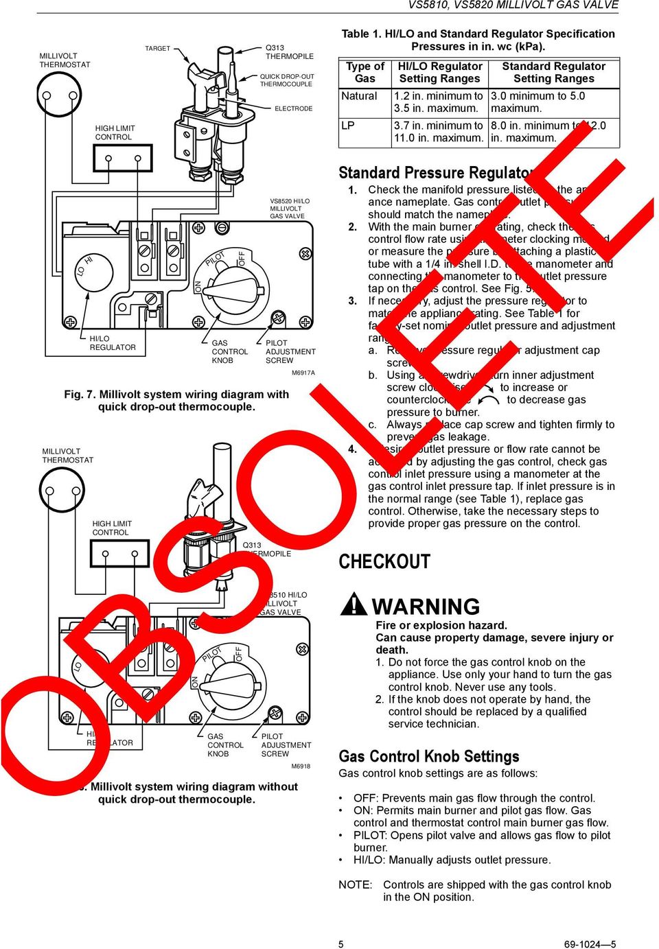
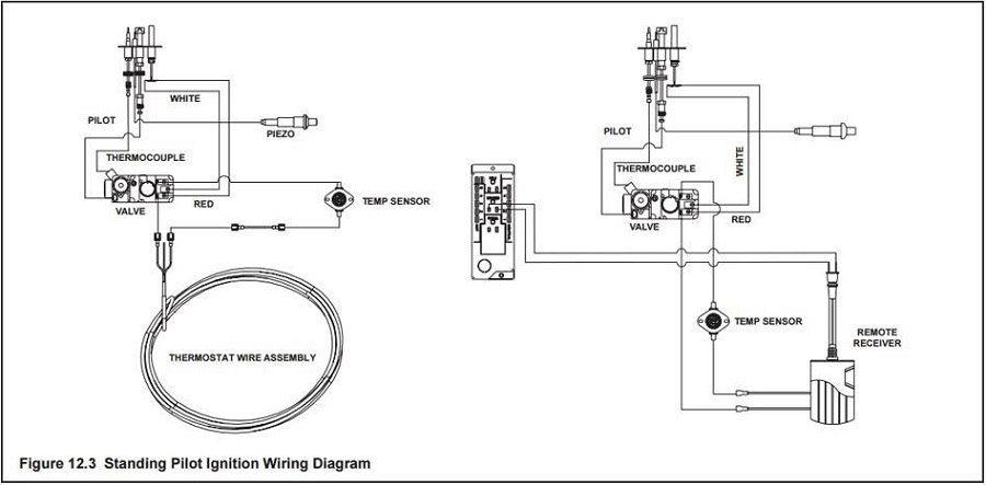
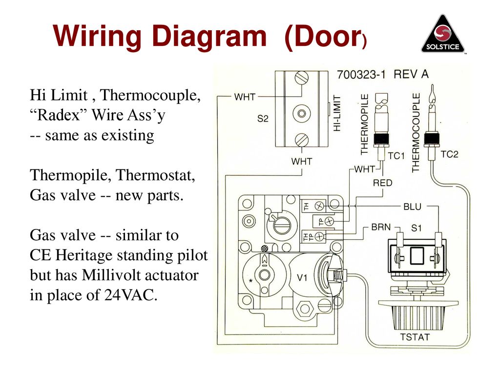
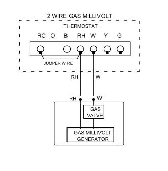
millivolt thermostat wiring diagram – What’s Wiring Diagram? A wiring diagram is a type of schematic which uses abstract pictorial symbols to demonstrate all the interconnections of components in a very system. Wiring diagrams are made up of certain things: symbols that represent the ingredients inside circuit, and lines that represent the connections between them. Therefore, from wiring ... a gas valve, thermopile, millivolt thermostat, and a pilot Millivolt system wiring diagram.DEAN MILLIVOLT GAS FRYERS (NON-CE) CHAPTER 3: INSTALLATION INSTRUCTIONS Gas Conversion Procedures See gas valve illustration below and gas valve, burner and orifice location on page when performing the following conversions. Knowledge about robertshaw gas valve wiring diagram has been uploaded by Benson ... Frymaster Dean millivolt fryers are also equipped with a high-limit thermostat. In the event that the fryer fails to properly control the oil temperature, the high-limit thermostat prevents the fryer from overheating to the flash point. The high-limit thermostat acts as a normally closed power switch that SIT Millivolt Wiring (See Figure 14) – 1 . Select any of the following optional controls: appliance-mounted (rocker switch) or wall- mounted switch, thermostat, or one of the optional remote control kits.
20.2.2015 · WIRING DIAGRAM NOTES: (Important, please read all notes before connecting wires) • If the information provided in the following wiring diagrams does not clearly represent or match your system, please refer to the “TECHNICAL ASSISTANCE” section of this manual, and contact us before removing any of your existing thermostat wiring.
710 502 Robertshaw Millivolt Dual Gas Valve 1 2 X Low Profile Amre Supply. Installation Data 700 720 Series Two Stage Gas Valves Wiring Diagrams. 700 C506 Robertshaw 750 Millivolt Dual Gas Valve 3 4 X Straight Thru Amre Supply. Robertshaw 662018634278 Gidds 506305 Low Profile Millivolt Combination Snap Action Gas Valve.
Detroit Radiant Products Company 21400 Hoover Road Warren, MI 48089. Toll-Free: 800-222-1100 Phone: 586-756-0950 [email protected]
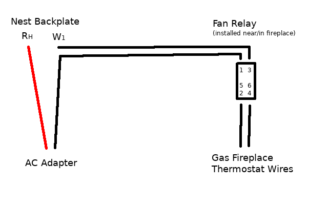
Connect W on the thermostat to one side of the relay coil. On the other side of the coil, you'll add C from the thermostat and common wire of the transformer. You're going to take the thermostat wires off your old millivolt thermostat and add them to the NO terminals on the relay. On a call for heat, the relay coil will be powered, closing the ...
Millivolt System The millivolt system and individual components may be checked with a millivolt meter having a 0-1000 MV range. Before checking system, be certain wall thermostat lead wire does not exceed length recommended in Wiring Section under "Millivolt Models" and all connections are clean and tight.
6.3.2021 · The easy-to-install Honeywell Home Manual Electric Baseboard Thermostat works on 4-wire (double pole) electric heat applications (baseboard or line volt) and allows for …
This is How to Wire the Thermopile to The 750mv Gas Valve for the Pilot and Main Gas Burners. This includes a WIRING DIAGRAM. I show you how to Light the Pil...
10.8.2011 · Of course, if current levels are to be determined such as Ii in the original diagram, the effect of RB must be included. Applying Kirchhoff’s voltage law to the input circuit of Fig. 10.24 will ...
Millivolt Thermostat Wiring Diagram. Print the wiring diagram off plus use highlighters to trace the signal. When you make use of your finger or perhaps the actual circuit with your eyes, it is easy to mistrace the circuit. 1 trick that We 2 to printing a similar wiring plan off twice. Upon one, I’ll trace the current movement, how it ...
Millivolt Thermostat Wiring Diagram. By Rocky Jamesh | August 10, 2020. 0 Comment. Milivolt systems w modern thermostats 0 item s 00 menu home detailed wiring diagrams nest thermostat to a gas fireplace millivolt models nmv 2 pmv infra system using 24v transformer you may be trying access this site zone valve diagram amkmns pilot generator 120v lwc on white rodgers ...

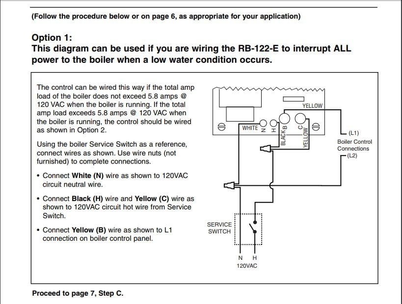
Wire the Nest to the inputs on the cheat-box. Rh and C on the Nest, which connect to R (T) and C, deliver 24V AC power to the thermostat from the big square yellow-ish transformer. (I have no idea ...
The new thermostat I purchased is a millivolt one, and the millivolt wiring diagram I was referring to was the one supplied with the new thermostat. I hope this clears things up a bit. Based on that, should there be a problem getting this to work ? The fireplace manual only shows hooking it up to a wall switch.

thermostat wiring. • All of the dashed wires shown in the wiring diagrams are either optional, or their usage depends upon your specific system type or brand. For example: Diagram #1 shows the fan wire as optional. If your system does not have a fan, than this terminal will not be used.
Millivolt Thermostat Wiring Diagram from inspectapedia.com Effectively read a electrical wiring diagram, one has to learn how the particular components inside the program operate. For example , in case a module is powered up and it also sends out a new signal of half the voltage plus the technician will not know this, he would think he provides a challenge, as this individual would expect a ...
Figure 2. Typical wiring diagram for heat only, 3-wire, single transformer systems TRANSFORMER Heating System Fan Relay Y RC JUMPER WIRE B O For 2-wire Heat only, attach to RH and W NOTE Y RH 24 VAC 120 VAC Hot Neutral TRANSFORMER THERMOSTAT SYSTEM G W Figure 3. Typical wiring diagram for cool only, 3-wire, single transformer systems Cooling ...
With a few tools you can easily wire a millivolt thermostat to your heating, ventilating and air-conditioning system. Advertisement Video of the Day Step 1 Turn off the electricity to your heating unit, such as a furnace or boiler. Step 2 Connect one thermostat wire to one screw terminal on your millivolt thermostat's wall plate. ...
Electrical (110V and millivolt) components and wearable parts such as blowers, gas valves, thermal switch, switches, wiring, remote controls, ignitor, gasketing, and pilot assembly are covered and NAPOLEON will provide replacement parts free of charge during the first year of the limited warranty.


0 Response to "38 millivolt thermostat wiring diagram"
Post a Comment