40 phase lock loop block diagram
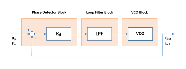
The block diagram of a phase locked loop. (11.35) f ref = f d = F out N or (11.36) F out = N f ref Since the divisor N is easy to change in practice, a wide range of frequencies can be generated from a single reference. These frequencies have the accuracy and long-term stability of the original reference. The diagram for a basic phase locked loop shows the three main element of the PLL: phase detector, voltage controlled oscillator and the loop filter. In the basic PLL, reference signal and the signal from the voltage controlled oscillator are connected to the two input ports of the phase detector.
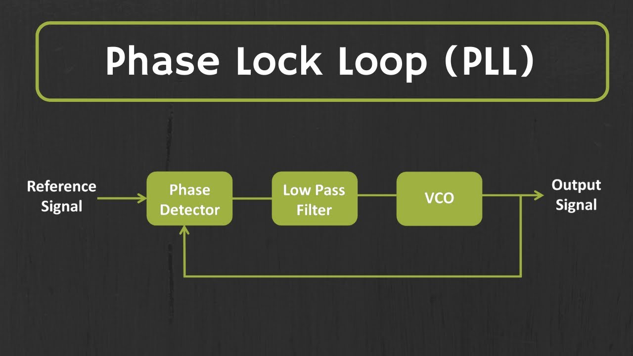
In this video, i have explained Phase Lock Loop by following outlines:1. Phase Lock Loop2. Basics of Phase Lock Loop3. Need of Phase Lock Loop 4. Block Diagr...

Phase lock loop block diagram
The open-loop control system block diagram is shown below. In the following diagram, the input can be given to the control system so that the required output can be obtained. However, this obtained output cannot be considered using this system for additional reference input. Definition: Phase-locked loops are the circuits used to maintain synchronization between input and output frequency of oscillator circuits by comparing the difference in phase of the two signals.With the evolution of IC, it has emerged as the basic building block of electronic circuits. Phase-locked loops are abbreviated as PLL and are basically a feedback circuit comprising of a phase ... The below figure shows the block diagram of the PLL. Phase-Locked Loop Detector. The phase-locked loop detector compares the input frequency and the output frequency of the VCO to produces a DC voltage which is directly proportional to the phase distinction of the two frequencies. The analog and digital signals are used in the phase-locked loop.
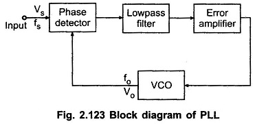
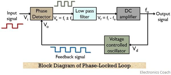
Phase lock loop block diagram. Block Diagram - Phase Locked Loops The input signal Vi with an input frequency fi is passed through a phase detector. A phase detector basically a comparator which compares the input frequency fiwith the feedback frequency fo .The phase detector provides an output error voltage Ver (=fi+fo),which is a DC voltage. Phase-locked loop (PLL) A phase-locked loop (PLL) is a feedback circuit designed to allow one circuit board to synchronize the phase of its on board clock with an external timing signal. PLL circuits operate by comparing the phase of an external signal to the phase of a clock signal produced by a voltage controlled crystal oscillator (VCXO). LECTURE 080 - ALL DIGITAL PHASE LOCK LOOPS (ADPLL) (Reference [2]) Outline • Building Blocks of the ADPLL • Examples of ADPLL Implementation • ADPLL Design • ADPLL System Simulation Lecture 080 - All Digital PPLs (5/15/03) Page 080-2 ... N before M Loop Filter Block diagram: v1 v2' PFD Tags Analog integrated circuit Block Diagram of Phase-Locked Loop capture range. centre frequency Lock range Phase-Locked Loop Phase-Locked Loop Applications. Share this post; Earthquake measurement Previous Post . Polymer Matrix Composites Next Post . About the Author. By tanweer. July 10, 2021 ...
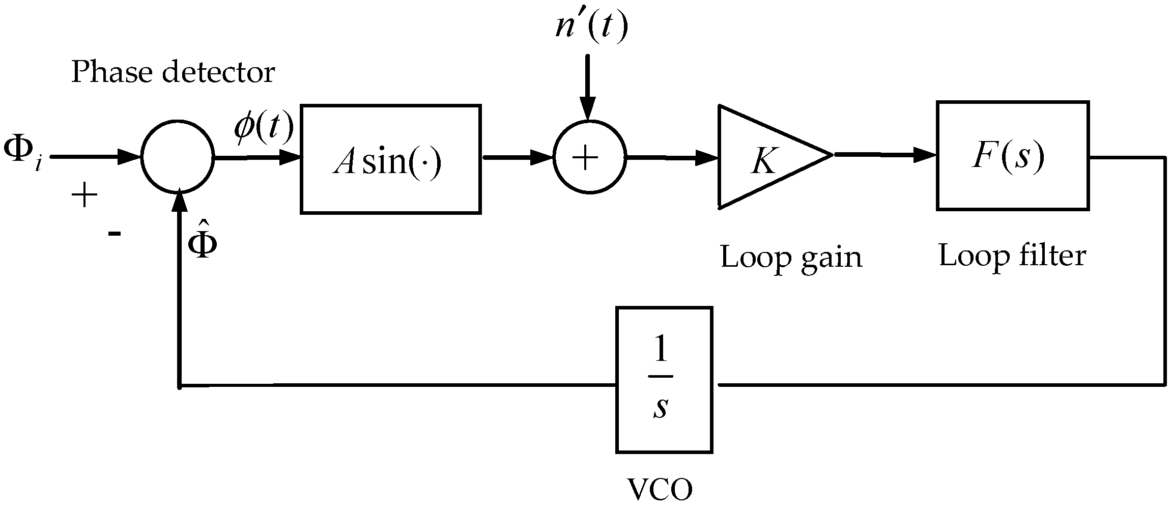
C. Three-phase PLL design A block diagram displaying the functional components of a generic PLL is shown in Figure 3. For small deviations, standard simplifying assumptions [7] allow the PLL to be modeled according to the linear block diagram of Figure 4, where t is the phase of the measured voltage and p is the phase estimate given by the PLL. A block diagram of a phase-locked loop circuit looks like this: Determine what type of electronic signals would be seen at points A and B for the following input conditions: Input = sine wave, steady frequency. Input = sine wave, increasing frequency. Input = sine wave, decreasing frequency. Input = sine wave, frequency increases and decreases ... Ve-max = ± KD π/2 When the phase detector output voltage is applied through the loop filter to the VCO, ∆ωout - max = ± KV π/2 = ωL (lock range) where KV = KO KD, the product of the phase detector and VCO gains. This is the frequency range around the free running frequency that the loop can track. The figure-1 depicts Block Diagram of Phase locked loop i.e. PLL Circuit in order to explain PLL working operation. PLL mathematical equation can be expressed as Fo = Fr * N , Hence Fo can be changed to different values within the range in either of the following ways. 1. keeping Fr fixed and varying N 2. Keeping N fixed and varying Fr.
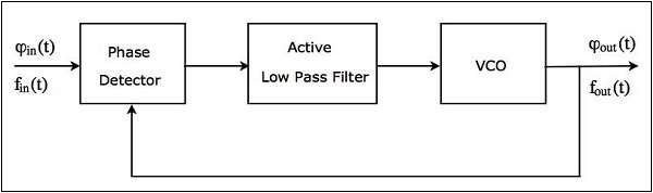
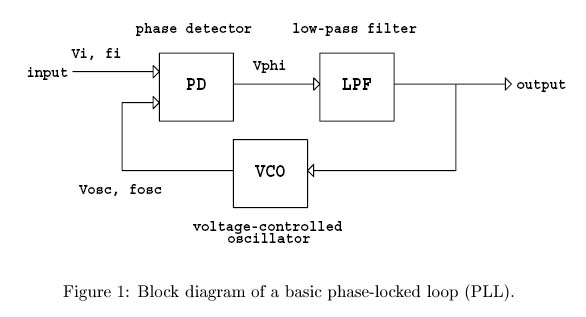
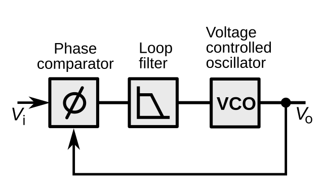
Block Diagram While a lock-in amplifier is an extremely important and powerful measuring tool, it is also quite simple. The block diagram of a lock-in amplifier is shown in Figure 1. The lock-in consists of five stages: 1. AC amplifier, called the signal amplifier; 2. … Block diagram of a PLL. We can readily model a PLL at this level in VHDL-AMS. We implement the phase detector as an analog multiplier, the loop filter as a lag block and the VCO as a gain block whose output frequency is determined by the following relationship: (23-1) f v c o ( t) = f c + K v v l f ( t) Block Diagram of PLL A Phase Locked Loop (PLL) mainly consists of the following three blocks − Phase Detector Active Low Pass Filter Voltage Controlled Oscillator (VCO) The block diagram of PLL is shown in the following figure − The output of a phase detector is applied as an input of active low pass filter. Block Diagram A PLL operates like a typical feedback system. It updates the output frequency of VCO until it matches the frequency of the input signal i.e. in sync with the input signal. Concept Of Operation The operation of Phase locked loop is based on the phase difference between the input and output signals.
Phase-Locked Loop (PLL) Fundamentals | Analog Devices
The complete diagram of a three phase LCL filtered including the control unit design with the proposed method is shown in Fig. 5(a). For better understanding of control unit, the three phase vector quantities i.e. grid current I g x , PCC voltage V p c c x , and capacitor current I c x are converted into α β stationary coordinate system using abc → α β transformation ( Blaabjerg et …
Phase Locked Loop (PLL) in a Software Defined Radio (SDR ...
The phase locked loop, PLL is a very useful RF building block. The PLL uses the concept of minimising the difference in phase between two signals: a reference signal and a local oscillator to replicate the reference signal frequency.
![Activity: The Phase Locked Loop. [Analog Devices Wiki]](https://wiki.analog.com/_media/university/courses/electronics/a31_f1.png?w=600&tok=cae073)
Activity: The Phase Locked Loop. [Analog Devices Wiki]
Two phase commit works across cluster nodes storing different values. For example, across different partitions of a database. Each partition can be using Replicated Log to replicate the state involved in two phase commit. The essence of two phase commit, unsurprisingly, is that it carries out an update in two phases:
Applied Sciences | Free Full-Text | Investigation of Phase ...
The digital phase-locked-loop block diagram of a magnetic hard-disk read channel shown on F ig.1 is referred to the paper presented by T oshio Murayam a in 1996 [2]. 8. Fig.1 Magnetic hard-disk read channel diagram By means of the Verilog-A hardware description language, the behavior

Effect of time delay on the pull-in range of phase locked ...
2.1 Phase Locked Loops (PLL) A phase locked loop is a device which generates a clock and sychronizes it with an input signal. The input signal can be data or another clock. The best known application of PLLs is clock recovery in communication. When an signal of a known frequency is being recieved often a
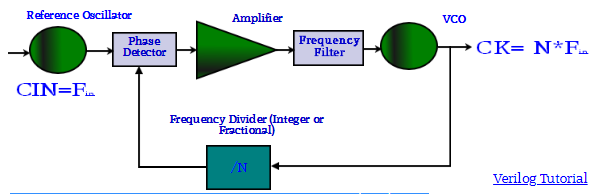
PLL for ASIC and fpgas. VCO, Phase detector, amplifier ...
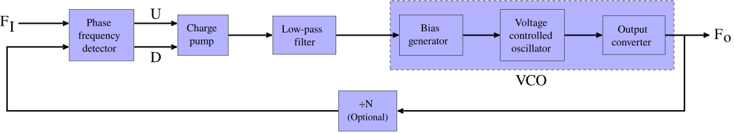
The figure shows the block diagram of the phase locked loop system in FM transmitter that consists of different blocks such as a crystal oscillator, phase detector, loop filter, voltage controlled oscillator (VCO), and frequency divider. Crystal Oscillator It is the most important part of the phase locked loop system.
Phase Locked Loops, block diagram,working,operation,Design ...
04-02-2022 · The phase locked loop can be analyzed in general as a negative-feedback system with a forward gain term and a feedback term. A simple block diagram of a voltage-based negative-feedback system is shown in Figure 1. Figure 1. …

Phase Locked Loop Operating Principle(हिनà¥à¤¦à¥€ )
02-02-2022 · The wider the loop bandwidth, the faster the lock time. The trade-off is that a wider loop bandwidth will reduce attenuation of spurious products and increase the integrated phase noise. Increasing the loop bandwidth significantly (>PFD/5) may cause the loop to become unstable and permanently lose lock.

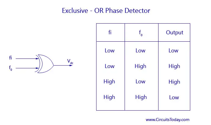
The Working Of Phase Detector In PLL - ADSANTEC
Block diagram: x(t) PFD QA QB VDD Cp I1 I2 S1 S2 VCO y(t) Fig. 2.2-20 The charge pump and capacitor Cp serve as the loop filter for the PLL. The charge pump can provide infinite gain for a static phase shift.

Phase Locked Loop (PLL) and Delay Locked Loop (DLL) Basics ...
Phase Locked Loop Block Diagram ÖN Ref Div Loop Filter VCO Phase Locked Loops (PLL) are ubiquitous circuits used in countless communication and engineering applications. Components include a VCO, a frequency divider, a phase detector (PD), and a loop lter. Niknejad PLLs and Frequency Synthesis Phase Locked Loops
Phase Locked Loop IC
With the block diagram and the transfer functions of components, a Linear Time Invariant (LTI) model can be developed to represent the PLL. The closed-loop transfer function of the DPLL model is then derived: (16) ... Introduction to phase-locked loop system modeling ...
Phase Locked Loop Working Principle | PLL block diagram ...
Block Diagrams Phase Locked Loop Tutorial The Phase Locked Loop (PLL) synchronizes a local oscillator with a remote one. This ensures that the local oscillator is at the same frequency and in phase with the remote one. The local oscillator is voltage controlled (it is a VCO).

Phase Locked Loop System Working and Applications
For phase-locked loop circuits, the bandwidth of the low-pass filter has a direct influence on the settling time of the system. The low-pass filter is the final element in our circuit. If settling time is critical, the loop bandwidth should be increased to the maximum bandwidth permissible for achieving stable lock and meeting phase noise and ...

Demo: Phase Locked Loop
4 CD4046B Phase-Locked Loop: A Versatile Building Block for Micropower Digital and Analog Applications 3 CD4046B PLL Technical Description Figure 2 shows a block diagram of the CD4046B, which has been implemented on a single monolithic integrated circuit. The PLL structure consists of a low-power, linear VCO and two

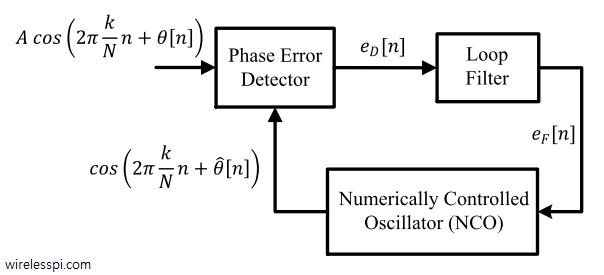
Simulink Exercises for "Digital Communications: A Discrete ...
A phase-locked loop or phase lock loop (PLL) is a control system that generates an output signal whose phase is related to the phase of an input signal. There are several different types; the simplest is an electronic circuit consisting of a variable frequency oscillator and a phase detector in a feedback loop.The oscillator generates a periodic signal, and the phase detector …

Demystifying phase-locked loops - Embedded.com
Describe the basic block diagram of the phase locked loop (PLL). A phase locked loop is basically a closed loop system designed to lock the output frequency and phase to the frequency and phase of an input signal. They are used in applications such as frequency synthesis, frequency modulation/demodulation, AM detection, tracking filters, FSK ...
What is Phase Lock Loop (PLL)? How Phase Lock Loop Works ? PLL Explained
The below figure shows the block diagram of the PLL. Phase-Locked Loop Detector. The phase-locked loop detector compares the input frequency and the output frequency of the VCO to produces a DC voltage which is directly proportional to the phase distinction of the two frequencies. The analog and digital signals are used in the phase-locked loop.

Phase Locked Loop Tutorial - Block Diagrams - Electronics ...
Definition: Phase-locked loops are the circuits used to maintain synchronization between input and output frequency of oscillator circuits by comparing the difference in phase of the two signals.With the evolution of IC, it has emerged as the basic building block of electronic circuits. Phase-locked loops are abbreviated as PLL and are basically a feedback circuit comprising of a phase ...

Phase Locked Loop System Working and Applications
The open-loop control system block diagram is shown below. In the following diagram, the input can be given to the control system so that the required output can be obtained. However, this obtained output cannot be considered using this system for additional reference input.
Lab_6,7,8) Phase Lock Loop - D.Son978

Basic introduction of Phase Locked Loop (PLL) | sHaRiNg is ...

Frequency and phase locked loops - EDN

Direct loop gain and bandwidth measurement of phase-locked ...
System-Level Tutorial Lesson 4: Exploring Phase-Locked Loops ...
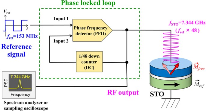
Extremely Coherent Microwave Emission from Spin Torque ...
Reference Clock/Phase-Lock Loop - NI High-Speed Digitizers ...

PLL Phase Locked Loop: How it Works » Electronics Notes

Phase Lock Loop - abisceg
What are Phase-Locked Loops (PLL)? Definition, Block Diagram ...
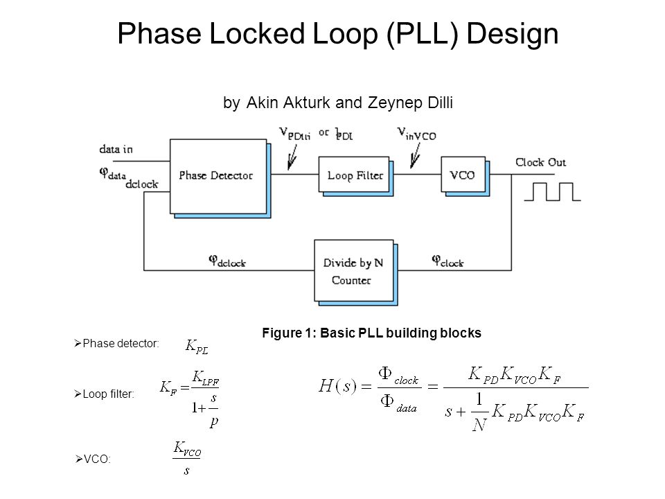
Phase detector:  Loop filter:  VCO: Phase Locked Loop ...
Phase-locked loop - Wikipedia

Demo: Phase Locked Loop

Electrical and Electronic Engineering: Phase Locked Loop (PLL)

Phase Locked Loops - an overview | ScienceDirect Topics
Phase-locked loop - Wikipedia
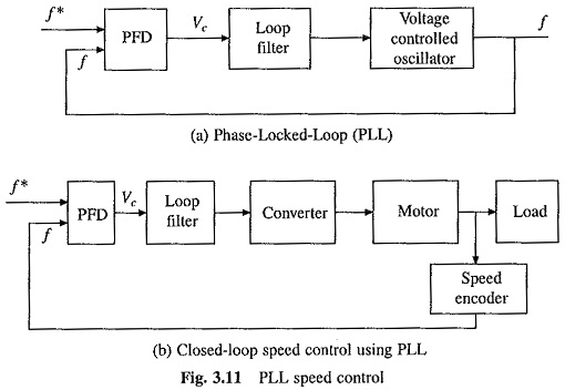
Phase Locked Loop Control | PLL Speed Control | Closed Loop ...

PLL Phase Locked Loop: How it Works » Electronics Notes
Phase locked loop and synchronization methods for grid ...

Describe the basic block diagram of the phase locked loop (PLL).

Phase-Locked Loop (PLL) Fundamentals | Analog Devices
0 Response to "40 phase lock loop block diagram"
Post a Comment