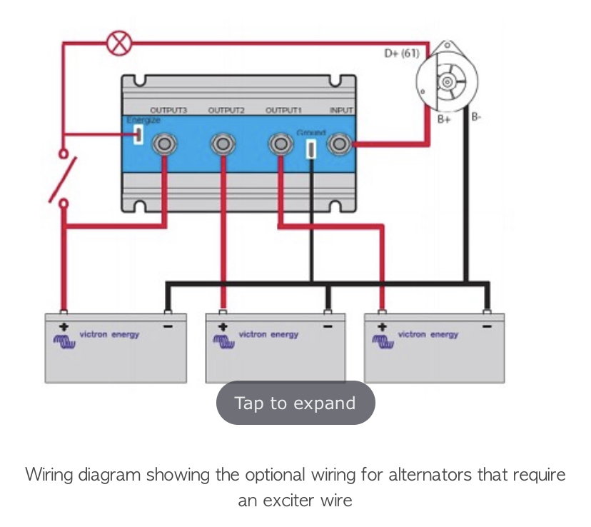
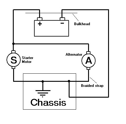
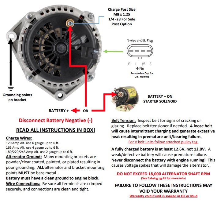
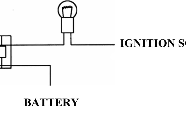
40 alternator exciter wiring diagram
Is Exciter wire needed on Alternator? | EY.o Information ... As per the original Universal wiring diagram, I do not see a wire connected to the exciter terminal on the alternator, but only a purple wire to the sensing terminal. However, as per the Mando alternator wiring diagram, there is a wire on both the exciter terminal and the sensing terminal. 12 Volt Alternator Wiring Diagram - Wiring Diagram Alt Wire Diagram Alternator Wiring And Out The Dash Warning Light - 12 Volt Alternator Wiring Diagram. Wiring Diagram arrives with several easy to stick to Wiring Diagram Directions. It's supposed to assist all the typical user in developing a suitable method. These guidelines will likely be easy to grasp and apply.
Alternator Exciter Wiring Diagram - Wiring Diagram Microcontroller - How To Monitor An Alternator Exciter Wire With Mcu - Alternator Exciter Wiring Diagram Wiring Diagram contains numerous in depth illustrations that present the connection of assorted items. It consists of guidelines and diagrams for different varieties of wiring methods and other items like lights, home windows, and so forth.
Alternator exciter wiring diagram
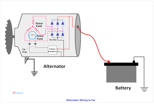
Alternator Wiring Diagram: A Complete Tutorial | EdrawMax An alternator wiring diagram will help you get the basic know-how of the circuit and how the components are linked together in a circuit. So, without further ado, let’s dive in. ... Exciter wire is connected to the L terminal of an alternator and is used to turn on the voltage regulator. Excitor wire is needed to generate the voltage required ... PDF How To Wire Alternator - Vintage Auto Garage Figure 1: DA Plug connects to the coil + terminal through the ballast resistor if there is one. Charge wire connects from the alternator to the battery through the the resistor or directly to the key switch itself (switched side). This wiring configuration will excite the alternator to start charging when the engine is running at low RPM's. 3 Wire Alternator Wiring Diagram 🏎️ What Wires Go Where? What's crucial to note about the 3 wire alternator wiring diagram is that it can improve the electrical performance of your vehicle to meet your needs. A 3 wire alternator wiring diagram has three wires: the primary charge wire, a third wire that can jump between the regulator and the battery stud, and the exciter wire.
Alternator exciter wiring diagram. PDF Wiring Diagram For Mando Alternator Wiring Mando Alternator Wiring Best Free. 1967 Camaro Alternator Wiring Diagram reveurhospitality com. Is Exciter wire needed on Alternator Ericson Yachts. How to properly wire your Marine Alternator Fishing Tackle. Ford Alternator Wiring Diagrams Carsut Understand cars. Wiring Diagram for alternator 2 / 16 How to properly wire your Marine Alternator How do I wire my marine alternator? Many alternators require ignition voltage to initiate charging. You must verify that all required connections are connected to the proper terminal and have the correct voltage in order for the alternator to operate properly. Below you will find the most common alternator circuits used on marine applications. 9.0 GENERATOR, EXCITER, AND VOLTAGE REGULATION the '1/4-cycle' diagram. Peak output voltage is generated at each cycle point. As the armature continues to rotate, it again gets to a position of no voltage generation, shown in the ‘½-cycle diagram’. As the rotation continues, a voltage is again generated. A close examination of the wiring out of the armature reveals that the 4 Wire Alternator Exciter Wiring Diagram 1. Loop the red wire off the factory harness plug on the alternator to the big post on the rear of the alternator. 2. The other terminal is the exciter. This is what excites the field of the alternator. The following diagram shows the wiring for a typical 3-wire alternator connected to our Infinitybox system.
Self exciting (one-wire) Alternator fix Wiring Problems Self-Exciting Alternator makes no need for Alternator Wiring Diagram The Self-Exciting alternator is an alternator that has a special voltage regulator that doesn't need an ignition wire to activate it.This is usually based on a chevy alternator type and only requires a battery wire connected to the battery terminal. How to Excite an Alternator | Truck of Mine Through exciting the alternator, you correct voltage at the alternator for it to operate correctly. This voltage should be roughly 2.5, with nothing running. What is the Exciter Wire on an Alternator? An exciter wire is the one that generates the voltage needed to keep the alternator functioning when you start the car. 3610 Gehl Alternator Questions - Yesterday's Tractors Here is the back of my current alternator and a pic of the wires that hooked up to the alternator. I assume the exciter wire is the white wire with the rectangle plug on it? Kow Farmer ... 01-30-2022 16:42:04 White wire is actually orange according to your wiring diagram. Follow it back a little bit and you will see I think. Any way here is how ... Alternator Wiring Diagram - easywiring Alternator wiring diagram. A wiring diagram is a simplified conventional photographic depiction of an electric circuit. Each part ought to be placed and linked to other parts in particular way. This wiring configuration will excite the alternator to start charging when the engine is running at low rpm s.
PDF Batteries and Alternators - Wood-Mizer Alternator Testing You should have a reading of approximately14.5 to 14.9 vdc. If not, unplug the exciter wire and verify you have 12 vdc at the wire plug. If good, remove the plug from the exciter wire and plug it directly to the alternator "L" terminal. If now good, replace the exciter wire pigtail. PDF Understanding the Alternator - Autoshop 101 Understanding the Alternator • Four wires connect the alternator to the rest of the charging system. • B is the alternator output wire that supplies current to the battery. • IG is the ignition input that turns on the alternator/regulator assembly. • S is used by the regulator to monitor charging voltage at the battery. Alternator Exciter Wiring Diagram - Wirings Diagram According to earlier, the lines at a Alternator Exciter Wiring Diagram signifies wires. Sometimes, the wires will cross. But, it does not mean connection between the wires. Injunction of two wires is usually indicated by black dot on the intersection of two lines. There'll be primary lines which are represented by L1, L2, L3, and so on. PDF Mando Alternator Wiring Diagram File Type PDF Mando Alternator Wiring Diagram wiring diagram, there is a wire on both the exciter terminal and the sensing terminal. After the engine.May 01, · With the engine
Alternator Exciter Wire | PowerStrokeArmy I notice that on initial startup the alternator only puts out 70 amps and the batteries are at 11.5 volts, then the exciter wire jumps up then the amperage output will jump to 100 and the voltage jumps to 14 as soon as it does. I don't have a wiring diagram handy at the moment. Has anyone simply put the exciter wire to a switched ignition source?
Alternator Exciter Wiring Diagram Alternator Exciter Wiring Diagram loop the red wire off the plug to the post on the rear of the alternator . And if there isn't one, I connect the exciter wire to the ignition circuit, thru. White wire says "to alternator regulator exciter". It looks like you are using the wiring diagram for a internal regulator alternator but using a.
What Is an Alternator Exciter? - It Still Runs An alternator is an auto part that transmits power from the fuel system to the battery for operating vehicle accessories, such as the radio, headlights and air conditioning fans. A wire called an exciter generates the voltage needed for an alternator to start working once a vehicle is started.
Alternator Exciter Wire Light | Electronics Forum ... I wired the alternator according to the manufacturer's spec (POS, NEG, EXC to key on power source). I wired the ignition light (supplied with a switch panel that was purchased for this boat) into the alternator EXC wire in this fashion: Key-on power to the + side of the light, and the - side of the light to the EXC post on the alternator.
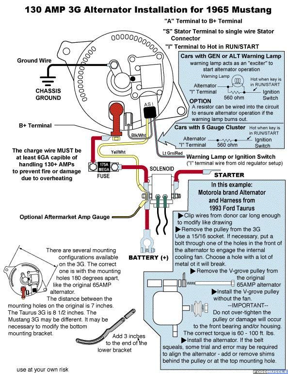
3-Wire Alternator - Infinitybox The other terminal is the exciter. This is what excites the field of the alternator. The following diagram shows the wiring for a typical 3-wire alternator connected to our Infinitybox system. Please refer to the manual and wiring diagram that came with your alternator for more specific details.
Wire Harness Installation Instructions - Painless Wiring turn switch, electric fan, horn, battery feed, alternator and alternator exciter wire, coil, and air conditioning. Included in the 18-circuit kit are trunk accessory, door locks, power windows, reverse switch and electric fuel pump.
Alternator Exciter Wiring Diagram - Cadician's Blog Microcontroller - How To Monitor An Alternator Exciter Wire With Mcu - Alternator Exciter Wiring Diagram Wiring Diagram contains numerous in depth illustrations that present the connection of assorted items. It consists of guidelines and diagrams for different varieties of wiring methods and other items like lights, home windows, and so forth.
10si Alternator Wiring Diagram The kits that I offer use a new 63 amp Delco 10SI cloned alternator. Each kit comes with a mounting bracket, tightener bracket, correct size pulley, diode/exciter wire, and wiring instructions and wiring diagrams. 10SI Alternator Wiring. The 10SI has three terminals (including those with a 1 wire regulator).
HONDA REBEL 250 SERVICE MANUAL Pdf Download | ManualsLib Honda ca125 rebel motorcycle owner's manual (302 pages) Motorcycle Honda CMX250C REBEL 2007 Owner's Manual. Honda cmx250c rebel (217 pages)
Wire Harness Installation Instructions - Painless Wiring This complete automobile wiring system has been designed with three major groups incorporated into it: ENGINE/HEADLIGHT GROUP Includes high beam, low beam, park, right turn, left turn, electric fan, horn, starter solenoid and battery feed, alternator and alternator exciter wire, distributor, water temperature, oil pressure, and air conditioning.
How to Excite the One Wire - Self Exciting Alternator ... visit:
Alternator Voltage Regulation 101 (with Wiring Diagrams ... A typical 3-wire alternator wiring diagram with an internal voltage regulator. Computer-Controlled Voltage Regulation. Many late-model vehicles use the engine computer, which is often referred to as the powertrain control module (PCM), to control alternator output. Most modules use an internal driver to turn the alternator's field circuit on ...
Laki-laki Ini Berupaya Setubuhi Tetangga ... - diefremden.de Feb 16, 2022 · Mr triton wiring diagram [email protected] We have provided you with a chart in Figure 23 with the resistance specifications for the solenoids. structure inside diagram mitsubishi montero wiring diagram new pajero pdf wiring diagram mitsubishi canter 2002, mitsubishi triton wiring diagrams engine diagram have a graphic from the other mitsubishi ...
Is there a wiring diagram for a 12 volt alternator ... According to earlier, the lines at a Alternator Exciter Wiring Diagram signifies wires. Sometimes, the wires will cross. But, it does not mean connection between the wires. Injunction of two wires is usually indicated by black dot on the intersection of two lines. What are the components of an alternator Exciter?
Alternator Wiring & Exciter | SailNet Community 13,641 Posts. #2 · Feb 10, 2016. Not knowing how your boat was originally wired, I'd try to find a wiring diagram from a sistership to see how that particular alternator was supposed to be installed. Or, contact the alternator maker and ask them--they're usually pretty good about it--how that exciter wire was supposed to be connected.
Alternator Exciter Wiring Diagram - schematron.org To Battery. Alternator. Basic wiring diagram to , replace the alternator and the exciter wire pigtail. However, as per the Mando alternator wiring diagram, there is a wire on both the exciter terminal and the sensing terminal. After the engine.May 01, · With the engine running at idle, my alternator is putting out 14 or so volts.
Wiring Diagram 3 Wire Alternator - U Wiring Alternator Wiring Diagram Wiring Diagram is the visual representation of a intricate electric circuit. A wiring diagram is a simplified traditional pictorial depiction of an electric circuit. The purpose is the very same. The following diagram shows the wiring for a typical 3-wireBatteries and Alternators.
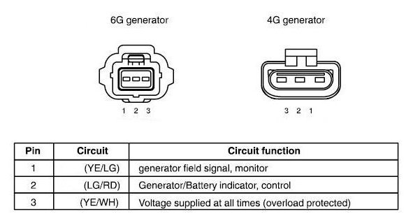
How to Understand Alternator Wires - It Still Runs This connector is manufactured so it may be inserted into the connector socket on the alternator one way only. If you are able to look at a manufacturer's diagram of the alternator's connectors, the wire that slides over Pin 1 of the alternator leads to the positive (+) connection on the vehicle's battery and senses voltage.
TRIUMPH - Motorcycles Manual PDF, Wiring Diagram & Fault … Feb 18, 2022 · Hi, does anyone have a wiring diagram for lexmoto assault efi 2019, the ignition switch they sell on cmpo doesn't fit to wiring loom on bike:))). They is a 6 pin plug with red, black and brown on bike and an 6 pin plug with red, black, green, black/white on ignition switch all of them in completely different positions. Guess what, bike doesn't ...
3 Wire Alternator Wiring Diagram 🏎️ What Wires Go Where? What's crucial to note about the 3 wire alternator wiring diagram is that it can improve the electrical performance of your vehicle to meet your needs. A 3 wire alternator wiring diagram has three wires: the primary charge wire, a third wire that can jump between the regulator and the battery stud, and the exciter wire.
PDF How To Wire Alternator - Vintage Auto Garage Figure 1: DA Plug connects to the coil + terminal through the ballast resistor if there is one. Charge wire connects from the alternator to the battery through the the resistor or directly to the key switch itself (switched side). This wiring configuration will excite the alternator to start charging when the engine is running at low RPM's.
Alternator Wiring Diagram: A Complete Tutorial | EdrawMax An alternator wiring diagram will help you get the basic know-how of the circuit and how the components are linked together in a circuit. So, without further ado, let’s dive in. ... Exciter wire is connected to the L terminal of an alternator and is used to turn on the voltage regulator. Excitor wire is needed to generate the voltage required ...










0 Response to "40 alternator exciter wiring diagram"
Post a Comment