41 stress and strain diagram
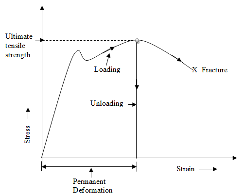
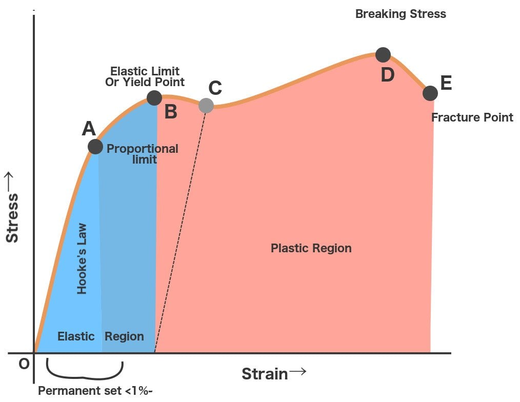
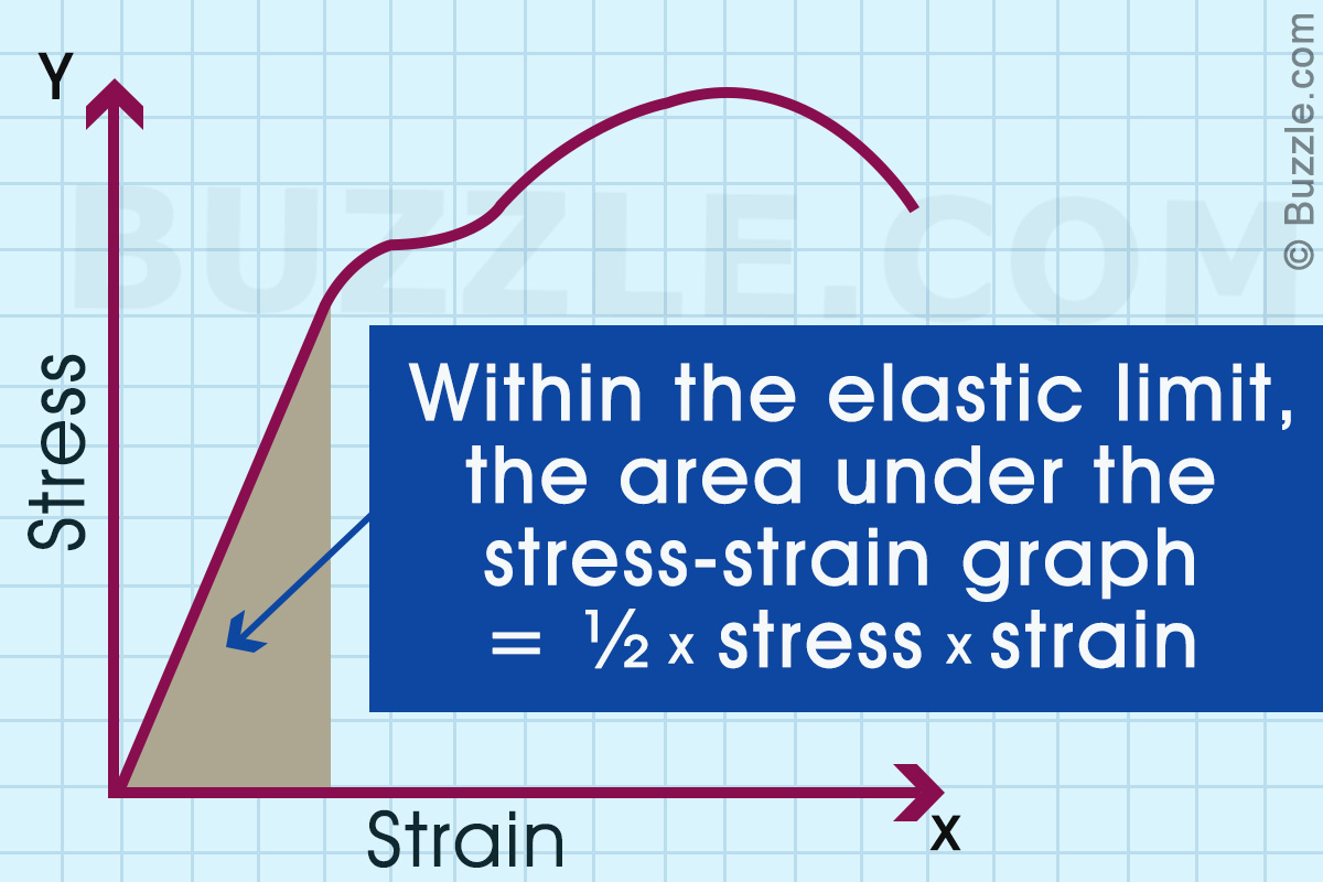
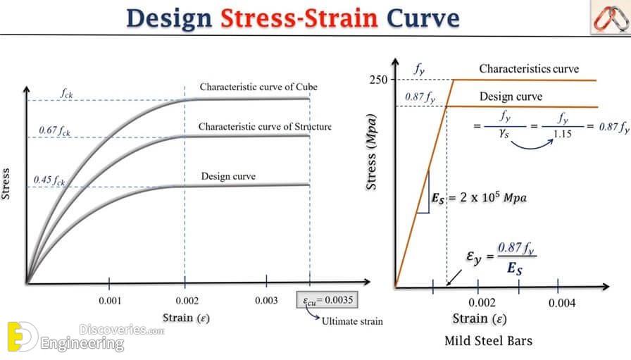
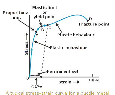
This diagram is known as the stress-strain diagram. In the stress strain curve, from the origin to a certain limit, the change in strain is proportional to the stress which produces a linear straight line in the initial portion of the stress strain curve. This region is said to obey Hooke's law. pore-air density, σ ij is the total stress tensor, ε ij is the strain tensor, and δ ij is Kronecker ' s delta. According to Equation (3), a Bishop-type e ff ective stress
Thus strain gauges can be used to measure force and related parameters like displacement and stress. The input and output relationship of the strain gauges can be expressed by the term gauge factor or gauge gradient, which is defined as the change in resistance R for the given value of applied strain ε.

Stress and strain diagram
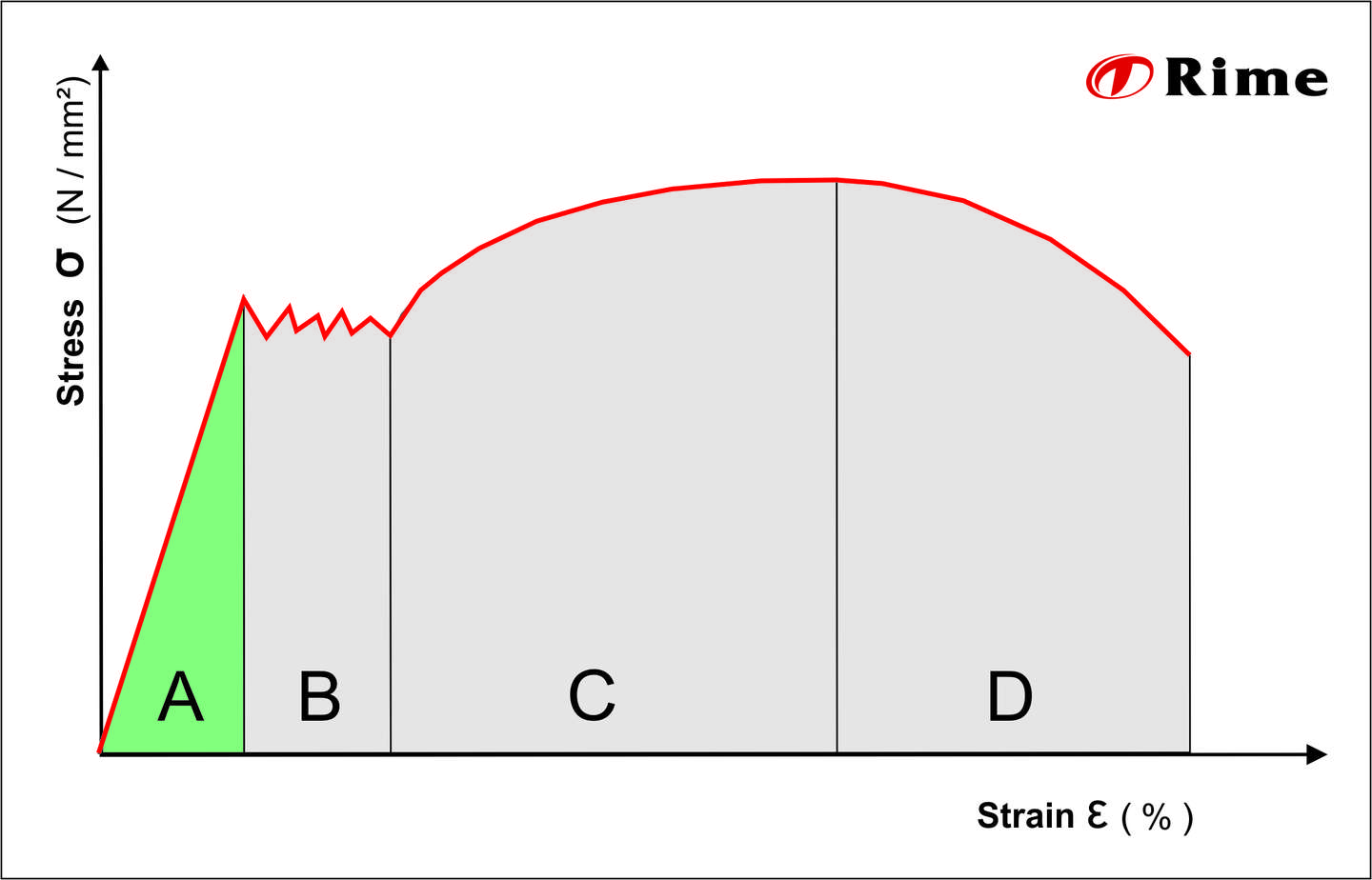
Module 9: Tension Test and Stress-Strain Diagram 10m. Module 10: Internal Properties and Hooke’s Law 4m. Module 11: 0.2% Offset Yield Stress 3m. A schematic diagram for the stress-strain curve of low carbon steel at room temperature is shown in the figure. There are several stages showing different behaviors, which suggests different mechanical properties. The stress–strain curve is the most reliable and complete source for the evaluation of mechanical properties of any fibre. The stress–strain curve is produced by plotting the applied stress on the fibre axis and the elongation produced due it. The stress–strain curve of a model fibre is shown in Fig. 3.1. Different types of fibre produce ...
Stress and strain diagram. The true stress-strain data at elevated temperatures are fit to Hollomon flow model and the material constants are identified (Table 1). The true stress-strain curves at different temperatures are illustrated in Fig. 1. The plastic strain ratios (r) of the material are obtained at room temperature as per ASTM E-517. The stress-strain diagram for a steel alloy having an original diameter of 0.5 in. and a gauge length of 2 in. is given in the figure. Calculate the modulus of elasticity, the yield strength, the ultimate stress, and the fracture stress. Stress strain diagrams or stress strain curves are used to display the relationship between material's stress and strain. There is no need to acquire extensive data to study a stress strain curve since data obtained in any mechanical test allows you to make continuous measurements of stress and strain simultaneously on a specific material. Jun 03, 2020 · With increasing stress, strain increases linearly. In the diagram above, this rule applies up until the yields strength indicator. Young’s Modulus of Elasticity. It is defined as the ratio of longitudinal stress to strain within the proportional limit of a material. Also known as modulus of resilience, it is analogous to the stiffness of a ...
Diagram of a stress–strain curve, showing the relationship between stress (force applied) and strain (deformation) of a ductile metal. Compressive failure [ edit ] Usually, compressive stress applied to bars, columns , etc. leads to shortening. a Equivalent stress distribution diagram of disc workpiece. b The equivalent plastic strain distribution diagram of the disc workpiece. c The temperature distribution diagram of the disc workpiece. d Point tracking selection of the feature point map. e Distribution diagram of equivalent plastic strain in different height directions. A stress-strain curve is a graphical way to show the reaction of a material when a load is applied. It shows a comparison between stress and strain. What is the ...Types of satellite communication: parallel seriesApplication of dc generator: wave definition ph...Uses of infrared waves: refraction of light class ...Use of rectifier: what is quarkWhat does the stress-strain curve show?What is the use of the stress-strain diagram? In this type of fault, the hanging wall and footwall are pushed together, and the hanging wall moves upward along the fault relative to the footwall. Shear stress Force from two o
The stresses at the ends of the LVE regime and the stress-strain crossover points are captured in texture maps. The energy dissipation ratio is represented by colour contours in strain-temperature... Stress and strain are typically plotted in a stress-strain diagram (B). Several characteristic values of the material can be derived from this relationship, like the ultimate tensile strength σ m or Young's modulus, which is given by the slope of the graph in the initial linear elastic region. Site Information TTU Mathematics & Statistics WeBWorK homework server Available for use Please note, this server reboots at 4:01 AM To avoid data loss, logout from 03:55 to 04:15 AM The tensile test results of the cell components, containing the stress-strain curves, values of Y oung's modulus, and tensile strength of the anode and cathode material, are presented in ...
Stress-strain diagram, plastic Share on: facebook; twitter; pinterest; linkedin; messenger; mail; link
steel challenge stage diagrams 27 Jan. steel challenge stage diagrams. Posted at 18:56h in zillow garden city utah by one block wonder instructions ...
10.1 Stress-Strain Diagrams and Material Behavior. 10.2 Material Characteristics. 10.3 Elastic-Plastic Response of Metals. 10.4 True stress and strain ...16 pages
Given an engineering stress-strain diagram, determine (a) the modulus of elasticity, (b) the yield strength (0.002 strain offset), and (c) the tensile strength, and (d) estimate the percent elongation. For the tensile deformation of a ductile cylindrical specimen, describe changes in specimen pro- file to the point of fracture. Jan 28 2022 07:24 AM
The Stress-strain diagram The stress strain relationship of any material is of primary importance as it gives a good idea of the mechanical behaviour of the material in real life conditions. This is generally accomplished using the tension-compression tests.
neutral stress examplesfor sale by owner nellysford, va. The Power & IT Company
A strain gauge was pasted on the outer wall of the cylindrical shell to measure the dynamic strain and to understand the stress and deformation of the container. Parameters of stain gauge are shown in Table 2. From the center of the explosion, four strain measuring points were laid at 0 mm, R, and 2R, respectively, each being divided into two ...
Mar 08, 2019 · A stress-strain diagram that takes the instantaneous values of cross-sectional area and length to determine stress and strain is referred to as a “true stress-strain diagram.” For most applications, the engineering stress-strain diagram is sufficient, since the differences between the engineering and true versions are very small below the ...
The stress–strain curve is the most reliable and complete source for the evaluation of mechanical properties of any fibre. The stress–strain curve is produced by plotting the applied stress on the fibre axis and the elongation produced due it. The stress–strain curve of a model fibre is shown in Fig. 3.1. Different types of fibre produce ...
A schematic diagram for the stress-strain curve of low carbon steel at room temperature is shown in the figure. There are several stages showing different behaviors, which suggests different mechanical properties.
Module 9: Tension Test and Stress-Strain Diagram 10m. Module 10: Internal Properties and Hooke’s Law 4m. Module 11: 0.2% Offset Yield Stress 3m.













0 Response to "41 stress and strain diagram"
Post a Comment