38 grasslin defrost timer wiring diagram
See wiring diagrams 8 & 9. 8240/6240 SERIES REPLACEMENT: The DTMV40 may be used to replace the Paragon 8240 or Precision 6240 series defrost timers with integral pressure termination the additionofa remotep essu e switchwi ed toter-Xp and p ofthe DTMV40 (with an 8240 series ter-label applied).The re must be noexte nal voltage Grasslin Defrost Timer Wiring Diagram On this website we recommend many designs about Grasslin Defrost Timer Wiring Diagram that we have collected from various sites of Wiring Diagrams Collections, and of course what we recommend is the most excellent of design for Grasslin Defrost Timer Wiring Diagram. DTAV See wiring diagrams 8 & 9.
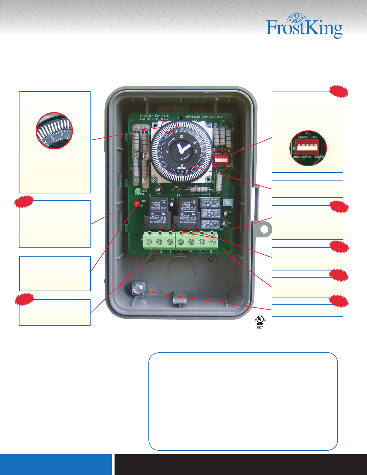
The DTAV40 Defrost Timer is equivalent in function, terminal identification (with appropriate terminal block label attached), and wiring to the Paragon 8140 and Precision 6140 series Defrost Timers. The DTAV40 may also be used to replace Paragon 8040 and Precision 6040 series time terminated defrost timers.

Grasslin defrost timer wiring diagram
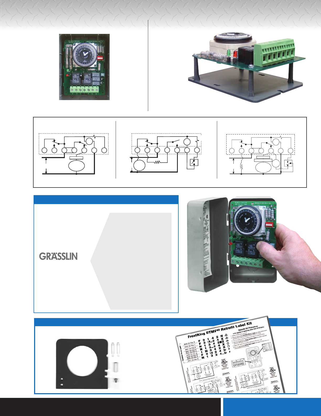
DTMV Time/Temp.-Electric Defrost Wiring Diagram 120V Fan & Defrost Heater; 240V Compressor 6 S1 Position A - No Label Required F 3 N 120V FAN 240V COMPRESSOR OR SOLENOID VALVE OR CONTACTOR COIL FAN MOTOR DEFROST HEATER L1 L2 TIMER TIMER RELEASE RELAY F 3 1-N 2 4 X LINE DTMV Time/Time -Electric Defrost Wiring Diagram 8045 Replacement 1 defrost timer shall incorporate voltage monitoring to protect against low-voltage conditions. The defrost timer shall also incorporate a short cycle delay adjustable from 0 sec. (off), 6 sec. minimum to 10 min. max to prevent rapid compressor cycling. The defrost timer shall be housed in a UL Type 3R indoor/ outdoor plastic enclosure. Grasslin Timer Wiring Diagram Grässlin UK Connect wiring in accordance with wiring diagram. Do not combine timer to control a load on a separate supply circuit, which can be a different. Wired incorrectly need wiring diagram. grasslin timer need to no what wires go were there are 4 wires coming out the timer red and brown together white and.
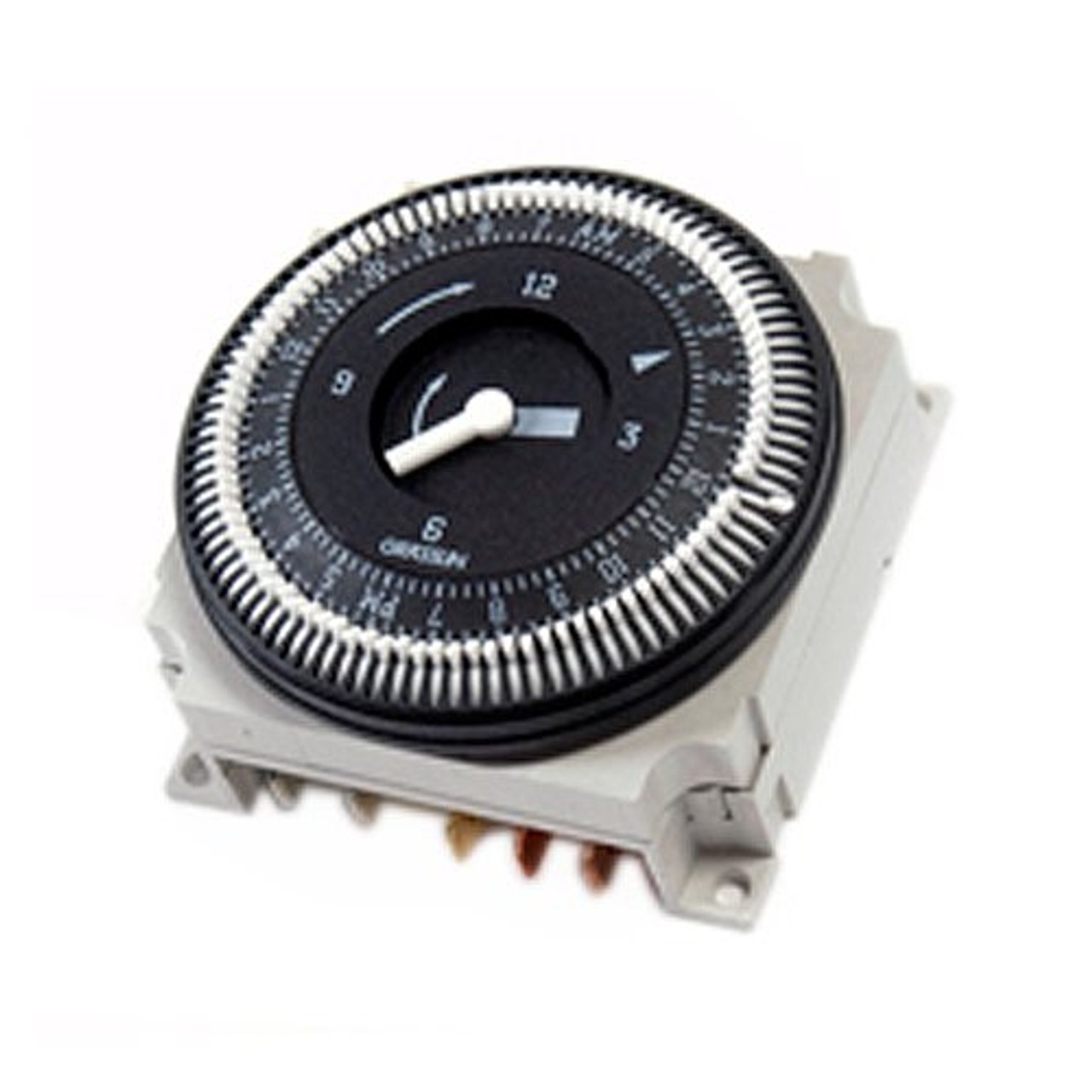
Grasslin defrost timer wiring diagram. In this video you can learn about the defrost timer wiring diagram of a frost free refrigerator and circuit diagram Step by step details about the function o... Set the correct time of day on the defrost timer. Do not set a cooler thermostat below the walk-ins design temperature or product Diagram 9 - Typical Wiring Diagram for Single with Defrost Timer Only.Jul 02, · I can increase the defrost time (Grasslin timer), but don't believe it will be the best solution. Dec 07, 2017 · Mechanical Defrost Timer 8000 Series. Grasslin dtmv40 series timer operating intermatic dtav40 installation heatcraft dtsz defrost time controls hvac r owner s manual required snaps into existing enclosures t 49f wiring diagram swapping on auto product catalog pages 101 instructions 831993 restaurant equipment parts model g8000 mechanical commercial refrigeration temperature dtav40q true ... Grasslin Defrost Timer Dtsx B 240 Wiring Diagram. Heatcraft grasslin dtsz defrost timer t 49f wiring diagram swapping on intermatic dtav40 series installation operating instructions warning risk of fire or electric shock refrigeration timers for controls dtsx b 240 time hvac r.
Grasslin Dtav40 Wiring Diagram For electric heat, hot gas or compressor shutdown defrost. The Grässlin DTAV40 Series Auto Voltage Defrost Timer is applicable to air defrost (compressor. Intermatic/Grässlin's Defrost controls just got even better! The DTAV40 defrost control automatically selects the appropriate voltage between Wiring Diagrams . Tired of clunky defrost timer replacements? Upgrade to the Grässlin by Intermatic DTAV40 and make installations a snap. In this quick installation walkthroug... DEFROST CONTROL Replaces • Grasslin: 010-0011B, DT040, DT140, DTAV40, DTMV, DTSX • Paragon: 8041, 8045, 8047, 8141, 8143, 8145, 8245, 8247 • Precision: 6041, 6045, 6047, 6141, 6145 • ICM550 defrost control module • Bracket mount • Installation guide • Terminal block & wiring diagram label sheet • #8 x 1/2" sheet metal screws (3) This item: Grasslin DTAV40, Universal Defrost Timer. $155.97. Only 10 left in stock - order soon. Ships from and sold by Commercial Kitchen Direct. FREE Shipping. Supco S8145-20 Complete Commercial Defrost Timer (Replaces Paragon 8145-20) $73.98. In Stock. Sold by PRIME DEALERS and ships from Amazon Fulfillment.
The Latest Paragon® Defrost Timer • Universal Defrost Timers (UDT) • Works with multiple voltages • Removes built up of ice and frost • Easy to install • Simple to program • Part 9145-00 temp terminated • Part 9045-00 time terminated • Available as mechanism only without case - Add "M" to end of part number So, what im hoping is, does anyone SA- WM250 Instructions ( primary manual) Subwoofer pdf manual download. Sam460ex manual transmission · Grasslin dtsx b 240 hc manual · Manual de grasslin categories topica 600 digital timer instructions dtsx b 240 hc wiring diagram by intermatic fm1d20 24u. grasslin gm40ave r tactic timer manual pdf time DTMV Time/Temp.-Electric Defrost Wiring Diagram 120V Fan & Defrost Heater; 240V Compressor 6 S1 Position A - No Label Required F 3 N FAN 1 2 0 V 2 4 0 V COMPRESSOR OR SOLENOID VALVE OR CONTACTOR COIL FAN MOTOR DEFROST HEATER L1 L2 TIMER T IMER R ELEASE RELAY F 3 1-N 2 4 X LINE DTMV Time/Time -Electric Defrost Wiring Diagram 8045 Replacement 1 Mar 24, 2019 · grasslin timer need to no what wires go were there are 4 wires coming out the timer red and brown together white and. Grässlin UK Connect wiring in accordance with wiring diagram. Do not combine timer to control a load on a separate supply circuit, which can be a different. schematron.org schematron.org Posted on Apr 21, Helpful 0; Not Helpful ...

How to wire GM40 GM40AV GM40AVE WHQ series
Grasslin Defrost Timer Wiring Diagram The Grässlin DTAV40 Series Auto Voltage Defrost Timer is applicable to air defrost (compressor shutdown) and electric or hot gas defrost systems where the . MODEL G Series Mechanical Defrost Timer. Installation Instructions. Figure 2. Snapping tabs off mechanism. Figure 3. Installing the G Defrost Timer.
Installation Instructions
These proficient grasslin defrost timer wiring diagram are available in modes such as manual and automatic versions depending on the models. Some of these cost-effective grasslin defrost timer wiring diagram found on the site are compressors, auto-defrost equipment, sterilization parts, piston kit, and many more to choose from.
Auto-Voltage Defrost Timer
True Freezer T 49f Wiring Diagram Grasslin Defrost Timer (Freezer Units Only). 13 TRUE will not warranty any refrigerator that has been .. louvered grill, wiring diagram is positioned on the. wires) N=White (Neutral) X=Purple (defrost termination) This info obtained from sheet included with the Grasslin Timer for the True Freezer.
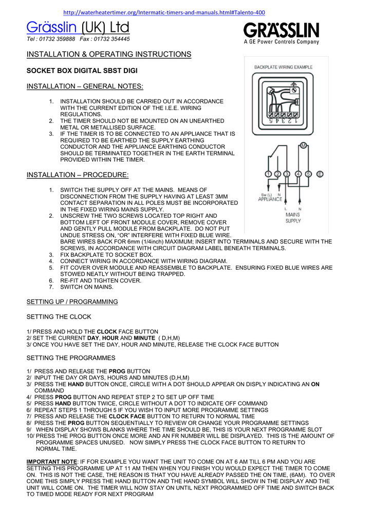
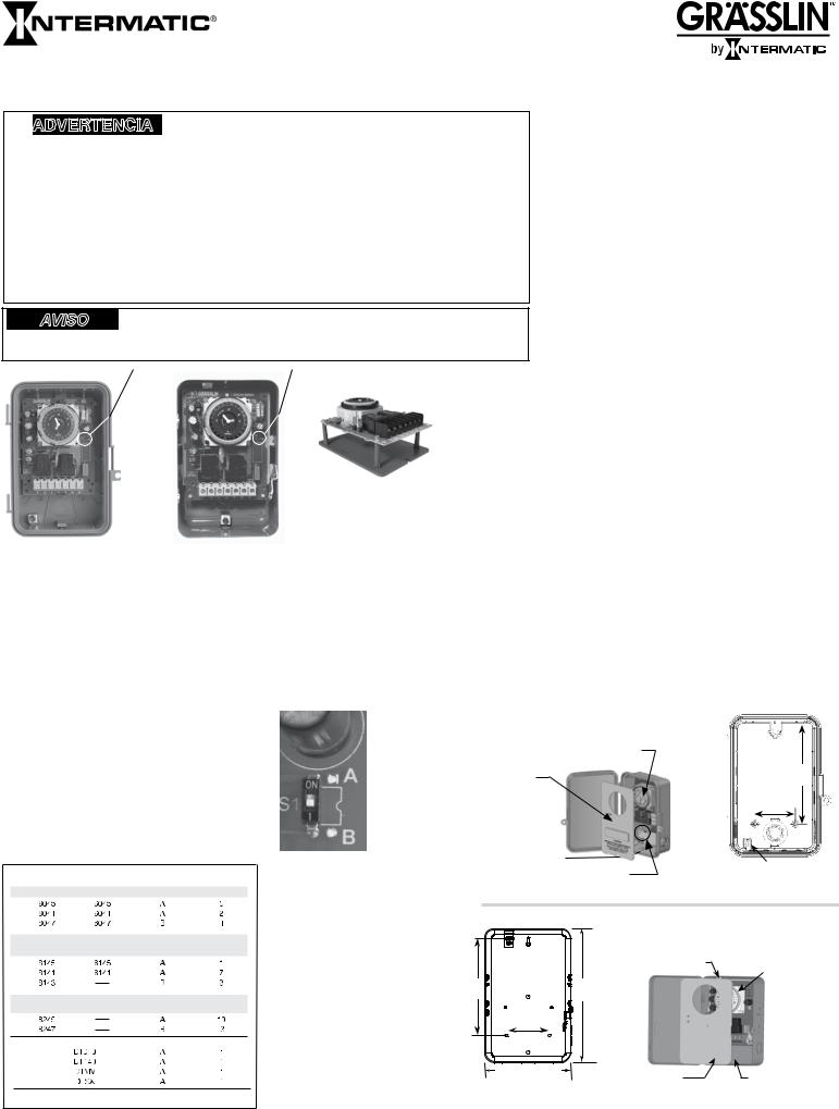
Grässlin (UK) Ltd INSTALLATION & OPERATING INSTRUCTIONS
Grasslin Timer Wiring Diagram Grässlin UK Connect wiring in accordance with wiring diagram. Do not combine timer to control a load on a separate supply circuit, which can be a different. Wired incorrectly need wiring diagram. grasslin timer need to no what wires go were there are 4 wires coming out the timer red and brown together white and.
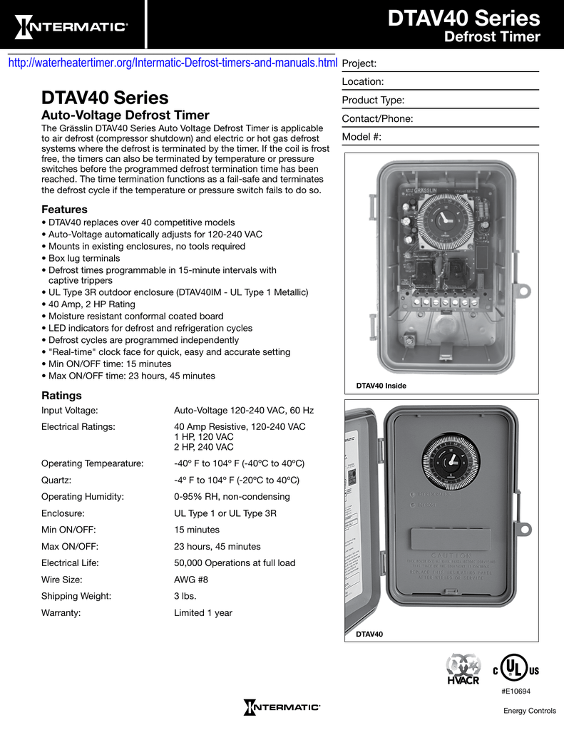
DTAV40 Series Defrost Timer Auto-Voltage Defrost Timer
defrost timer shall incorporate voltage monitoring to protect against low-voltage conditions. The defrost timer shall also incorporate a short cycle delay adjustable from 0 sec. (off), 6 sec. minimum to 10 min. max to prevent rapid compressor cycling. The defrost timer shall be housed in a UL Type 3R indoor/ outdoor plastic enclosure.

HOW FREEZER DEFROST TIMER OPERATES
DTMV Time/Temp.-Electric Defrost Wiring Diagram 120V Fan & Defrost Heater; 240V Compressor 6 S1 Position A - No Label Required F 3 N 120V FAN 240V COMPRESSOR OR SOLENOID VALVE OR CONTACTOR COIL FAN MOTOR DEFROST HEATER L1 L2 TIMER TIMER RELEASE RELAY F 3 1-N 2 4 X LINE DTMV Time/Time -Electric Defrost Wiring Diagram 8045 Replacement 1
REFRIGERATION
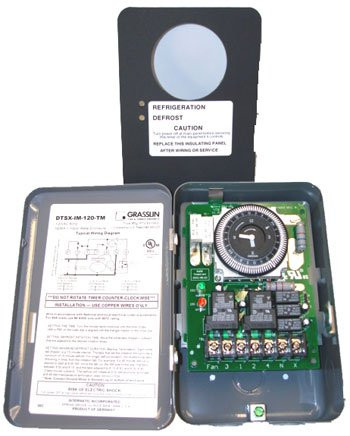
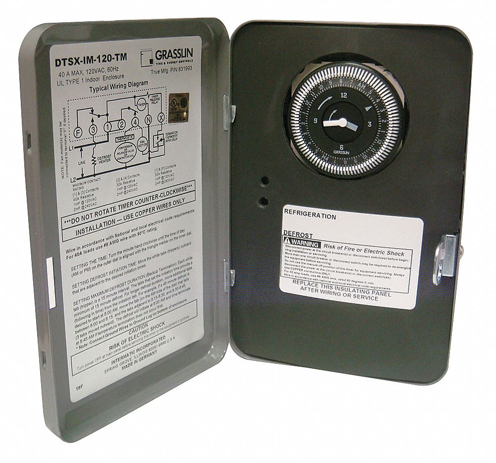
True 831993 - DTSX-IM-120-TM Defrost Timer by Grasslin
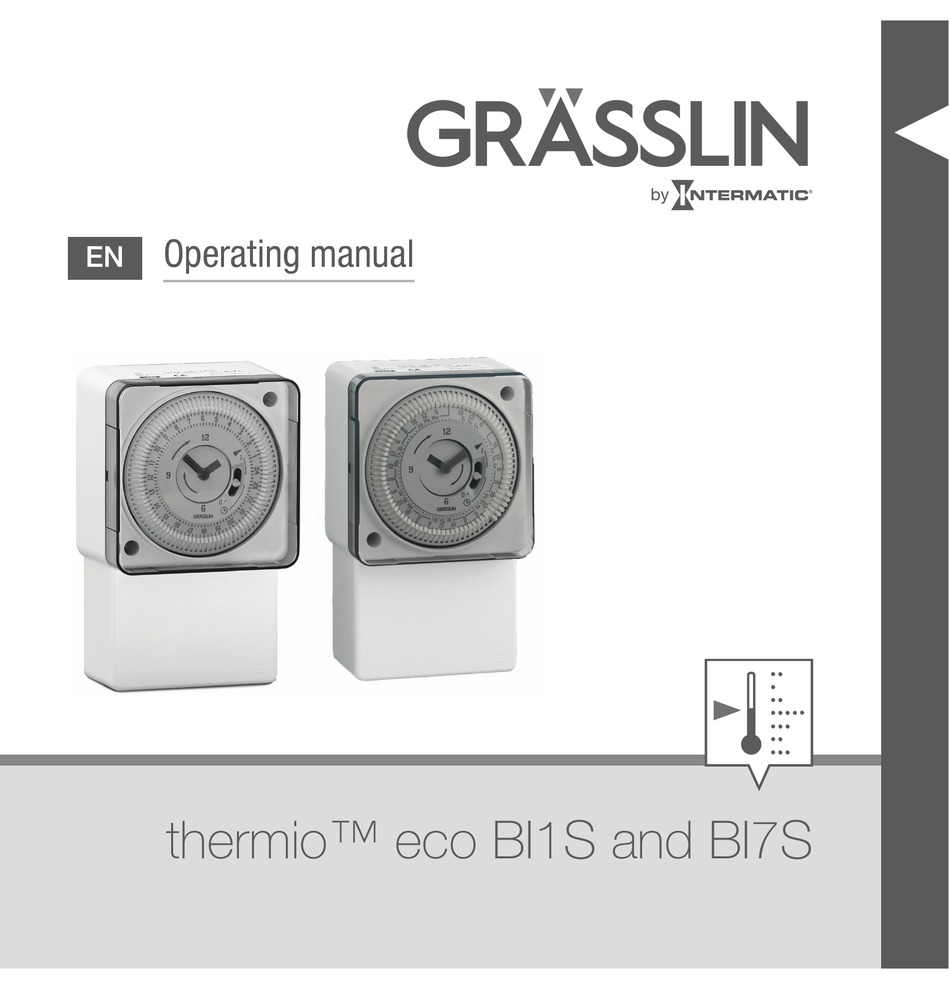
GRASSLIN THERMIO ECO BI1S OPERATING MANUAL Pdf Download ...

GRASSLIN DTMV40 SERIES TIMER OPERATING INSTRUCTIONS MANUAL ...

Heatcraft Grasslin DTSZ Defrost Timer Installation and ...
Intermatic defrost timer dtmv40

Using Defrost Termination and Fan Delay Controls | ACHR News

GRASSLIN DTAV40Q,DTAV40Q,Grasslin,GRASSLIN INTERMATIC,MECH ...
Intermatic defrost timer dtmv40

Grasslin DTMV40 Universal Defrost Timer
Defrost Timer

Grasslin DTSX-B-240-HC Defrost Timer | eBay

T-49f wiring diagram: Swapping timer on True T49F freezer ...

Amazon.com: Grasslin 120/208 Descongelar temporizador ...

Heatcraft Refrigeration Products H-IM-CU - page 20
Defrost / HVACR
DTSX Time Initiated, Temperature, Pressure or Time Terminated ...
PF1103T-wiring-diagram.gif | Trouble Free Pool

Streamline Defrost Timer Installations With Intermatic's ...
Multi-Voltage Defrost Timer
Digi 20 OI
Defrost Time Controls / HVAC/R Defrost Time Controls / HV AC/R
Defrost Time Controls / HVAC/R Defrost Time Controls / HV AC/R
True 831939 - FM1/STUZ Defrost Timer by Grasslin for TAC-48

DTAV40 Intermatic Grasslin Auto Voltage Defrost Timer

T-49f wiring diagram: Swapping timer on True T49F freezer ...
Appliance411 FAQ: How does a Frost Free Refrigerator's ...

Grasslin DTAV40 Defrost Timer – SWH Supply Company

Intermatic Defrost timers and manuals
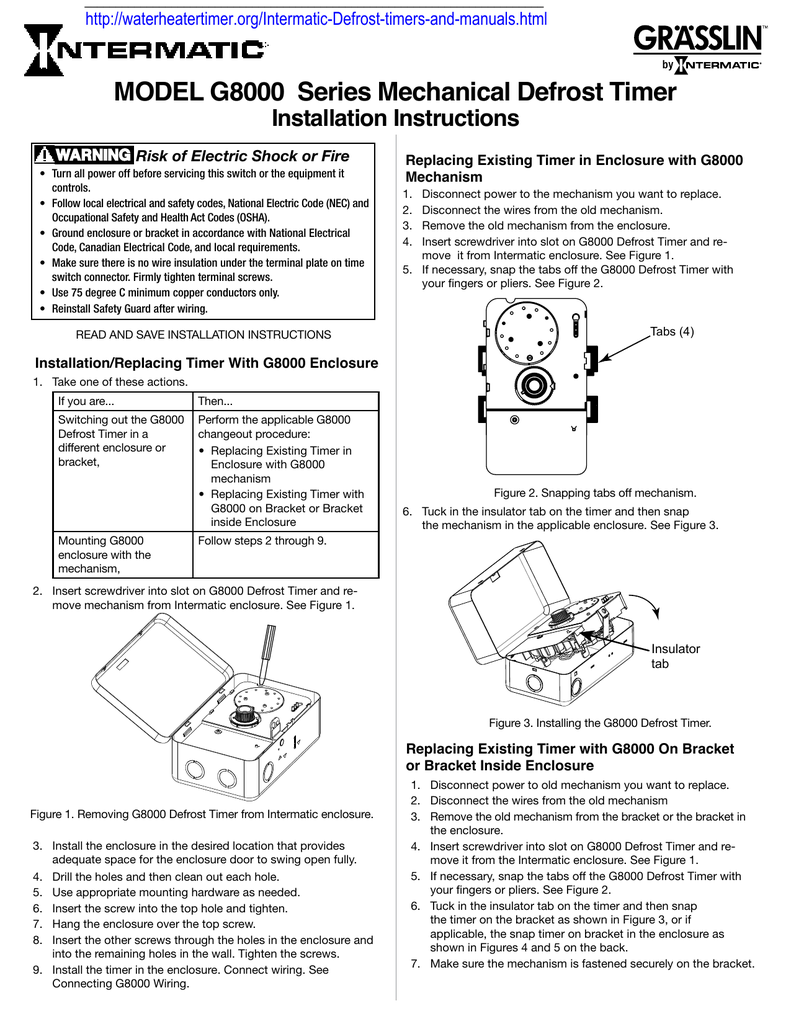
MODEL G8000 Series Mechanical Defrost Timer Installation ...
HVAC-Talk: Heating, Air & Refrigeration Discussion
Intermatic DTAV40 Series Owner's Manual
0 Response to "38 grasslin defrost timer wiring diagram"
Post a Comment