37 lewmar windlass wiring diagram
Wiring diagram using contactor provided ( Part No ) .. Is there voltage at the positive switch terminal on the solenoid. Pre & Custom Build Models. Can be used with all Lewmar custom windlasses, contact the sales office for a specific wiring diagram. Sprint , Atlantic. If your windlass is reversing it simply has an additional footswitch, solenoid . Follow the wiring diagram § 5.5 NOTE: • Optional electric footswitches and remote handheld control available. Visit www.lewmar.com for more information • Contactor box and control box used in some installation refer to wiring diagram § 5.6 and § 5.7 • Optional wireless remote also available. See table below for models and references
At P2 Marine we understand that when you need a part for your Lewmar windlass, you need it delivered quickly. This is why we stock all of the most common parts required to keep your windlass in service, and we place weekly orders to fill in for less common and special order parts.
Lewmar windlass wiring diagram
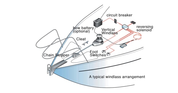
Issue #3: Your Electric Windlass Motor is Running but the Chainwheel Doesn't Turn. If the windlass motor runs, but the windlass isn't deploying or retrieving the anchor rode, the most common issue is with the clutch adjustment. Most windlasses have a clutch adjustment, which when loosened allows the chain to freefall. • Lewmar windlasses are designed and supplied for anchor control in marine applications and are not to be used in conjunction with any other use. • Keep limbs, fingers, clothing and hair clear of windlass, rode and anchor during operation. ... Figure shows a typical installation wiring diagram. ... 23.12.2021 · The latest Tweets from City of Calgary (@cityofcalgary). Official City of Calgary local government Twitter account. Keep up with City news, services, programs, events and more. Not monitored 24/7. Calgary, Alberta
Lewmar windlass wiring diagram. 1.6 Fitting the windlass to the deck 5 1.7 Fitting the motor gearbox 7 2. Electrical wiring installation 8 2.1 Electric cable selection 8 2.2 Wiring 8 2.3 Control switch installation 8 2.4 V1 Wiring diagram 9 3. Operating your windlass 10 3.1 Safety fi rst 10 3.2 Use of clutch 10 3.3 Letting go under gravity 10 3.4 Letting go under power 10 About Press Copyright Contact us Creators Advertise Developers Terms Privacy Policy & Safety How YouTube works Test new features Press Copyright Contact us Creators ... Issue 6.1 (March 2004) Thematic Issue: Shakespeare on Film in Asia and Hollywood. Ed. Charles S. Ross 4.2 Receiver wiring diagram WARNING! Connect only to a DC power supply 1. Figure 4.2-1 shows a typical installation wiring diagram. 2. Receiver is supplied with 2 or 4 relay outputs with one or two common contacts. Common contact must be connected to positive or negative pole, according to the polarity of the load connected.
The first step towards benefiting from the Netstrata difference is to make an enquiry for an obligation free quote. Request a Quote. If you would like to visit us, scroll down to see our office locations. 1.6 Fitting the windlass to the deck 5 2. Electrical wiring installation 7 2.1 Electric cable selection 7 2.2 Wiring 7 2.3 Control switch installation 7 2.4 V700 Wiring diagram (toggle switch) 8 2.5 V700 Wiring diagram (contactor) 8 3. Operating your windlass 9 3.1 Safety fi rst 9 3.2 Use of clutch 9 3.3 Letting go under gravity 9 Lewmar Windlass Wiring Diagram Name, Volt, Used on, Download wiring diagram Series Wound Dual Direction Contactor - /, 12/24V DC, Concept 3, V4 Windlass, Click here. Propose using lewmar dual direction contactor. The contactor has Wiring diagram for windlass shows 4 posts on contactor. Is it the case then. Pre & Custom Build Models. Can be used with all Lewmar custom windlasses, contact the sales office for a specific wiring diagram. Sprint 900, Atlantic, Atlantic A, Atlantic C, AP700, AP1000 & AP1200 : Use Diagrams A* or B Atlantic B & Concept / Ocean2 : Use Diagrams C or D - Sprint 3000 : Use Diagrams C or E *Contactor 0052531 is NOT suitable for these products.
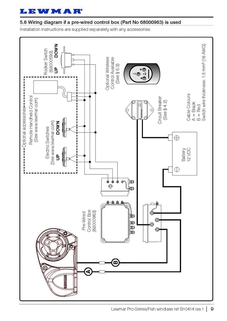
Lewmar windlasses are designed and supplied for anchor control in marine applications and are not to be used in conjunction with any other use. Keep limbs, fingers, clothing, and hair clear of windlass and anchor rope/chain and anchor during operation. ... Wiring diagram if a pre-wired control box (Part No 68000963) is used Installation ... Wiring Diagram 12/24VDC Used on: 140TT2.2KW; All 185TT, 250TT, 300TT To Thruster Black box Via Automatic Battery switch if fitted and/or P/S Battery switch if fitted 3 4 1 2 GREY BLUE RED BLACK GREY(BLACK-3) BLUE(BLACK-2) RED(BLACK-1) BLACK(GRN/YELL) 5432 1 5 BUTTON WIRELESS RECEIVER MODULE 68000968 876 For Terminals 1 to 5 Refer to windlass ... PDF. Postcolonial Studies in the Twenty-first Century: A Book Review Article of Literature for Our Times & Reading Transcultural Cities Alejandra Moreno Álvarez Lewmar CPX Vertical Windlass 66300104 Issue 2 D Installations-, Betriebs- und Wartungshandbuch F ... Electrical Wiring 14 ... 4.3 Control switch installation 15 4.4 Wiring diagram 16 5. Operation 17 5.1 Braked anchor free-fall 17 5.2 Power up/down 18 5.3 Optional manual recovery kits 19
How to: The Right Electric Windlass for Your Boat - Sail Magazine
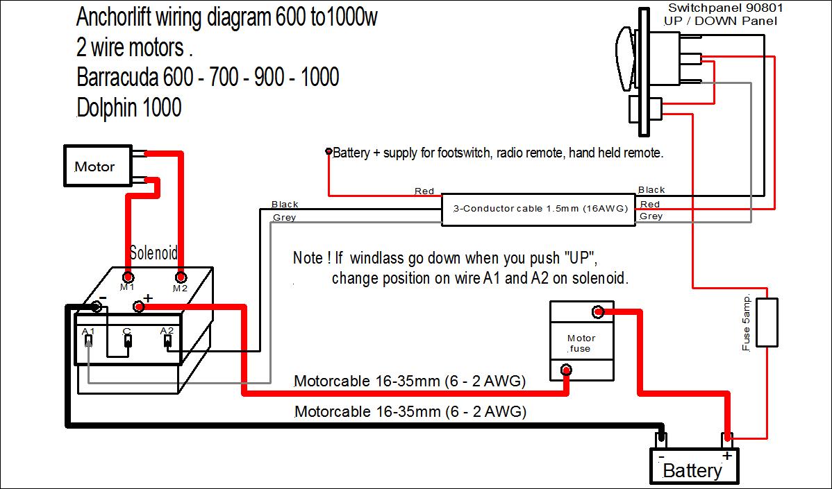
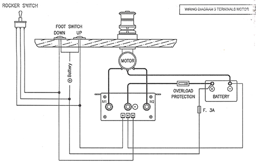
1. 2. GREY. BLUE. Lewmar windlasses are designed and supplied for anchor control in marine applications and are not to be . Wiring diagram using contactor provided ( Part No ) .. Is there voltage at the positive switch terminal on the solenoid. If your windlass is reversing it simply has an additional footswitch, solenoid .

Anchor Windlasses png images | PNGEgg
The wiring diagram that came with it is very generic and I.The original Windlass since Italian engineering and design. Apr 19, · As can be seen when comparing this video to the first video titled "Lofrans Tigres Horizontal windlass problems" The motor is running fast and strong.
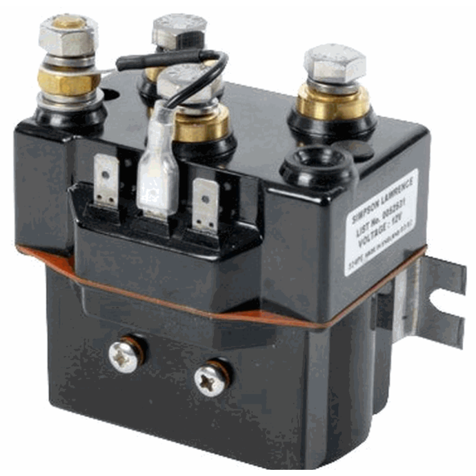
24V Dual Direction Sealed Contactor - for CPX4; V4, V6, V8-3500 Windlasses
May 07, · Lofrans Cayman 88 windlass - bodging the wiring lofrans windlasses puts the wiring diagrams up on the web: and the down by a blue wire from down button into the control box. the common power supply wire to both buttons is red, and has a 5 amp fuse and also a circuit breaker. Nov 17, · Jamestown Distributors TV: Retro-Fitting A ...
Lewmar Windlasses | Lewmar Windlass - Jimmy Green Marine
Lewmar Pro-Series/Fish windlass ref B iss.1 Page 8. Wiring diagram if a contactor box (Part No ) is used Installation instructions are supplied separately with any accessories. Page 9. Wiring diagram if a pre-wired control box (Part No ) is used Installation instructions are supplied separately with any accessories. Lewmar Windlasses.
Anchorlift - Control Units and Electrical Components
We finally moved everything out of the v-berth giving us clear access to our original Ideal windlass. It wasn't working the last time we tried it so today's ...
Bowsprit
Nov 24, 2017 · 1 Beitrag von Stephanie Pauly am November 2017 veröffentlicht. Eine neue Studie des @dipf_aktuell sowie der @goetheunifrankfurt zeigt, dass Student*innen mit Migrationshintergrund im Vergleich zu ihren weiteren Mitstudierenden ein geringeres Zugehörigkeitsgefühl zum Lehramtsstudium aufweisen.

Lewmar V700G Vertical Windlass 1/4 Kit
This will bypass both the switch and solenoid wiring the windlass motor directly to the power source. Do this for troubleshooting only to test that the solenoid is the only problem. Step 3: Use a voltmeter to check for voltage at the windlass motor. Put the positive probe on the electrical stud on the motor, the negative probe on

Lewmar Windlass Wiring Diagram Upgrade Windlass Power Wiring ...
• Contact Lewmar for correct fi tting of electrical connections. If the motor is unitentionally fi tted this way on a single speed winch it will not operate and make a clicking noise, on a 2 or 3 speed winch it will dramatically reduce performance. • Check clearance below deck and accessibilit y then position the

Anchor Windlass Up/Down Rocker Switch Panel, 12V FO-3739-M2
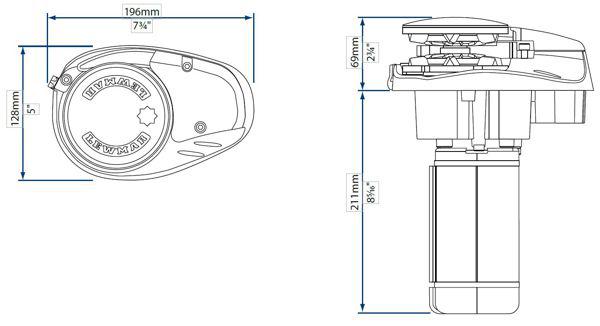
Lewmar V700 Vertical Windlass ref 65001022 iss.8 | 7 CABLE SIZING FOR LENGTH OF CABLE RUN 0 - 10 m 0 - 33 ft 11 - 18 m 34 - 60 ft 19 - 24 m 61 - 80 ft 10 mm2 8 AWG 16 mm2 6 AWG 25 mm2 4 AWG 5. Electrical wiring 5.1 Electric cable selection Plan the installation to suit the controls and give the operator a full view of the windlass. The wiring ...
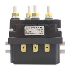
Lewmar Windlass Control Solenoid - 12 Volt DC (68000939)
Lewmar v700 2. Electrical wiring installation . 6V700 Windlass 7, 2. Electrical wiring installation, +, E, A, 2.1 Electric cable selection, 2.2 Wiring, 2.3 Control switch installat ion, 2.4 V700 Wiring diagram (t oggle switch), 3.1 Safety rst, 3.2 Use of clutch, 3.3 Letting go under grav ity
am F
Jamestown Distributors TV: Retro-Fitting A Lewmar Windlass: Wiring the Control Box. Power and Motoryacht Magazine's Ken Kreisler and Lewmar's Tom Fleming pr...

Wireless RF Remote Control kit | Lewmar
It appears that #4 guage wire runs from battery/circuit breaker to "contactor" then to motor it is probably #10 wire, 3 or 4 ft. The rocker switch clicks in one positio … read more. V700 lewmar windlass. Conected to a lewmar contactor.

Sailing Guide How to Install a Windlass | Force 4 Chandlery
Lewmar Pro-Sport/Series/Fish Windlass 65001242 Issue 3 D Installations-, Betriebs- und Wartungshandbuch I Guida all'installazione, all'uso e alla manutenzione S ... 4.4 Pro wiring diagram with contactor 14 4.5 Pro wiring diagram with contactor box 15 4.6 Pro wiring diagram with pre-wired control box 16 5. Operation 17
WINDLASS SWITCHES AND HAND HELD CONTROLLER.
Looking at Ralph wire diagram, it looks like he tapped off from the main power cable. Actually, that is the wiring diagram from the Lewmar installation instructions. Here's my as-built wiring. Seeing as I already had a 5A breaker for the windlass on my panel, I thought I'd use it as a...

Troubleshooting the Windlass - Boat and Equipment Reviews
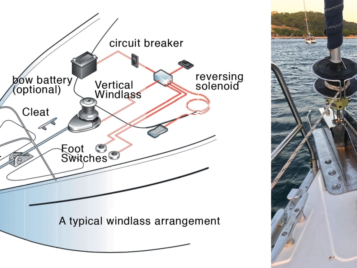
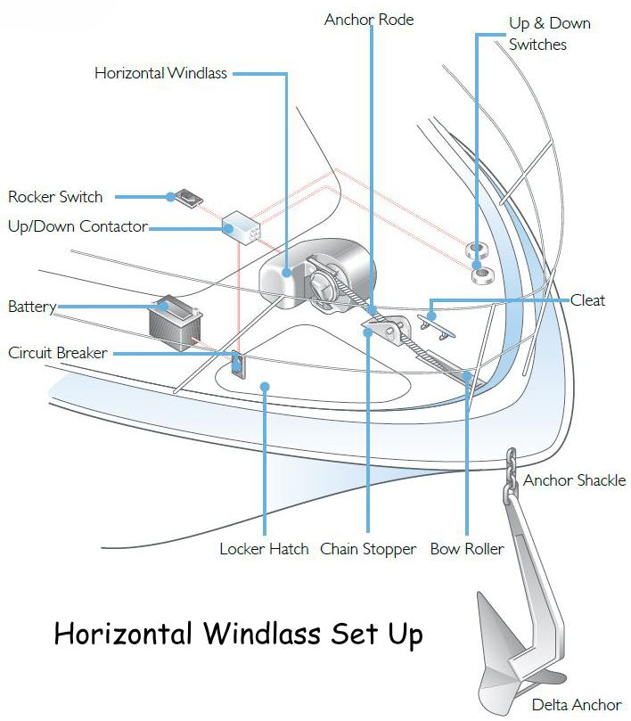
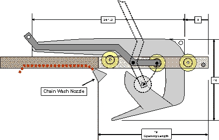
There are two types of electric anchor windlasses: horizontal-gypsy models with the unit fully enclosed above deck and vertical-gypsy models with much of the unit concealed below deck. Both automaticaly feed line and chain into the rode locker. We chose the Pro-Fish 1000 horizontal windlass from Lewmar , which has a free-fall function. This ...
Lewmar winch motor thermal cutout wires | Sailboat Owners Forums
Subaru's EJ205 was a 2.0-litre horizontally-opposed (or 'boxer') four-cylinder turbocharged petrol engine. In Australia, the EJ205 was available in the SF.II Forester GT from August 1998 and the GC.II/GM.II Impreza WRX from September 1998.

Amazon.com: Five Oceans Dual Direction Reversing Windlass ...
• Keep windlass wiring separate from other wiring, and connect to starter battery where possible. • The circuit breaker must be kept dry. • All switches must be wired in parallel. • The windlass operates in the correct direction from all switches. • That the windlass does not cause harmful electro-magnetic interference to other equipment.
Lewmar Vertical Windlass Problem - Cruisers & Sailing Forums
23.12.2021 · The latest Tweets from City of Calgary (@cityofcalgary). Official City of Calgary local government Twitter account. Keep up with City news, services, programs, events and more. Not monitored 24/7. Calgary, Alberta

Amazon.com: Five Oceans Dual Direction Reversing Windlass ...
• Lewmar windlasses are designed and supplied for anchor control in marine applications and are not to be used in conjunction with any other use. • Keep limbs, fingers, clothing and hair clear of windlass, rode and anchor during operation. ... Figure shows a typical installation wiring diagram. ...
Windlass wiring | Sailboat Owners Forums
Issue #3: Your Electric Windlass Motor is Running but the Chainwheel Doesn't Turn. If the windlass motor runs, but the windlass isn't deploying or retrieving the anchor rode, the most common issue is with the clutch adjustment. Most windlasses have a clutch adjustment, which when loosened allows the chain to freefall.
Imtra Watertight Control Box - 12V for 3 wire motors - 700 to ...

239fs lewmar windlass repair - KEY WEST BOATS FORUM

Lewmar 12V Windlass Control Solenoid Dual Direction 92235P 68000318 - NEW
LEWMAR V700 OWNERS INSTALLATION, OPERATION & SERVICING MANUAL ...
Lewmar free fall windlass Pro-Fish 700 6 / 7mm chain ...

Anchor Winch Electrical Problem - myHanse - Hanse Yachts ...
OWNER'S MANUAL AutoAnchor 570
Lewmar V700 Vertical Windlass

Lewmar Windlass Wiring Diagram Upgrade Windlass Power Wiring ...
Lewmar Electric Winch F*ckery - Fix It Anarchy - Sailing ...
Lewmar Foot Switch problem - Page 3 - Cruisers & Sailing Forums
How to: The Right Electric Windlass for Your Boat - Sail Magazine
Untitled

Lewmar® 6672211108-139 - V3 Series 890 lb 9/16" Line, 5/16" Chain Gypsy Only Vertical Line/Chain Windlass
ANyone know where windlass solenoid is located on pursuit ...

DRAFT AA560.1: Chain Only Wiring Foot Switches and Remotes ...
Lewmar winch motor thermal cutout wires | Sailboat Owners Forums
0 Response to "37 lewmar windlass wiring diagram"
Post a Comment