39 micro switch wiring diagram
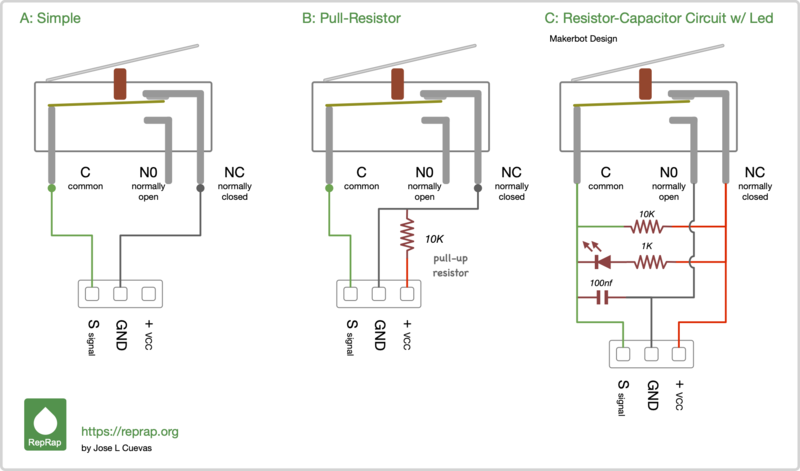
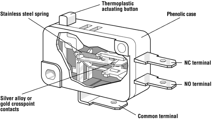
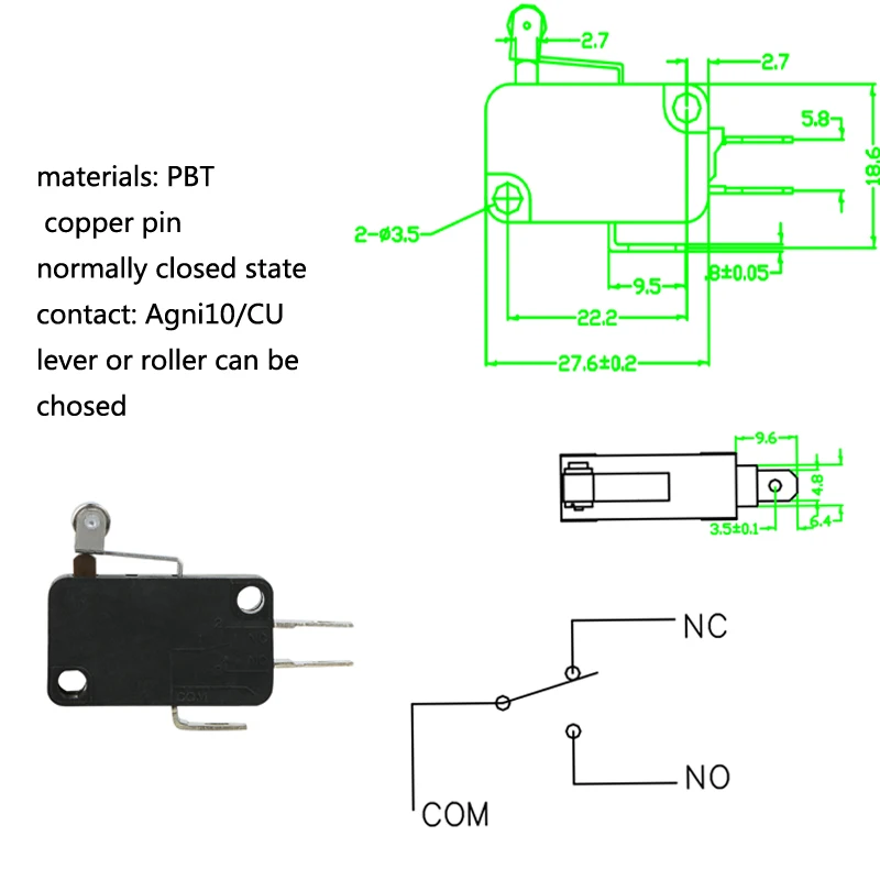
Nov 02, 2017 · The snap action switches have three output contact strips denoting common (C), open (NO) and closed (NC). When the switch is actuated, depending on how you wire, the contacts will open or close while the plunger is being pressed. Here’s a quick wiring diagram for your reference. JMP Snap Action Switches are a simple solution where ... Hi everyone, I am working to make a micro usb rechargeable strobe light with a power switch. The enclosure needs to be round, 2 inches in diameter, with a 1/4 inch hole through the middle (like a donut). I am using a variety of breakout boards to achieve a modular layout that will fit within the ring enclosure. Attached is my first attempt at a circuit diagram (not sure if I am wiring this correctly). I am brand new to all of this so any guidance and help would be very appreciated. Thanks!! [Ci...
Hello, I'm preparing for a big project that include few flashlights. I need to control them with only one remote switch without bypassing the UI/micro-controller (So I'm just making a remote switch for flashlights that don't have one). So I wanted to know how does tail switches and side e-switches work. My hypothesis is that the tail switches are connected in series with the battery and momentarily open the circuit when pressed quickly. If this is true, they are less suitable for a remote swit...

Micro switch wiring diagram
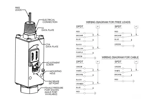
See DIAGRAM Connect a Blue wire from the key switch to terminal 2 on the Golf/Street switch, and the Brown wire to terminal 1. May 18, · Connect them both to load on the micro switch. Wire you hot common/line/live , and neutral to micro. The micro is now acting as load for anything that was previously connected to the wall switch. MICRO SWITCH™ V-Basic Standard V15 Series Switches ... A circuit diagram is included on the switch case labeling each of the terminals. Hello! So as I have stated in the title I have been trying to find a wiring diagram for a HyperX alloy FPS pro. I have a broken trace that connects the most left column of keys to the micro controller. I have been trying to figure out which pin it should connect to but I can't figure it out. Is there any way to figure it out without taking the switches out of the PCB?
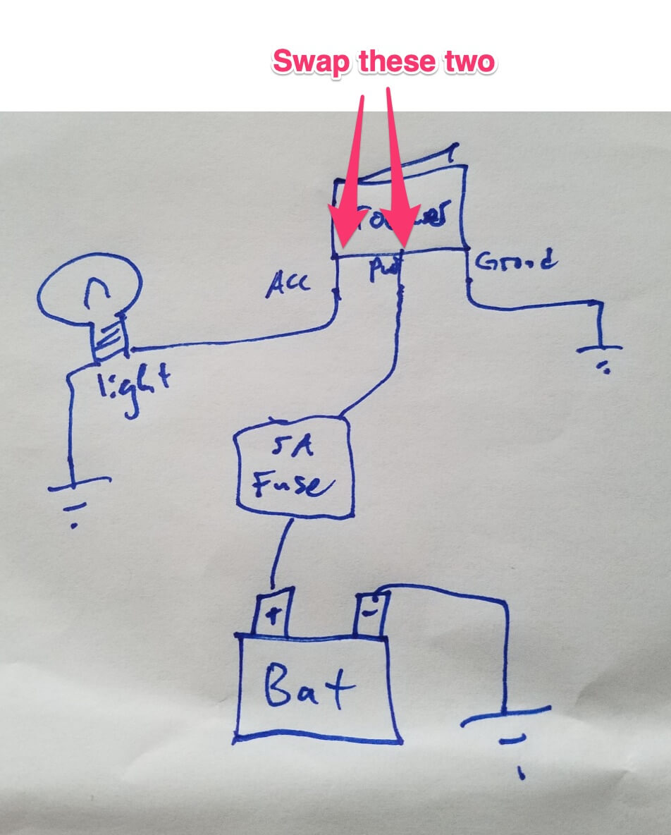
Micro switch wiring diagram. Oct 03, 2021 · Ansul micro switch. B8f Xantrex Charge Controller Wiring Diagram Wiring Resources. Run a low voltage wire from the 12v micro switch in the ansul system to the 12v shunt trips. If an ANSUL fire system is present the fire system micro – switch will need to be wired to terminals as indicated on the installation diagram. Hi so I think I'll need some help on this project I'm coming up with. I've got a partscastor and I'm modding the shit out of it. Its HSH (or will be when the time comes) and I'll put a list of what I want for controls. Basically I'm no electrician and I'm poor and dont want to outsource the physical wiring because i can follow a diagram. But I need help coming up with a diagram. If you are interested in being hired dm for more exact details of what ive come up with so far so we can collaborate. ... 1456 products — Browse industrial brands zone. Alibaba.com offers wiring diagram micro switch for your electric utilities to last long. wiring diagram micro ... See DIAGRAM Connect a Blue wire from the key switch to terminal 2 on the Golf/Street switch, and the Brown wire to terminal 1. Installation Instructions for the ISSUE 4 MICRO SWITCH™ Heavy Duty Limit Switch Series PK wiring and conduit connection is made to the base receptacle.
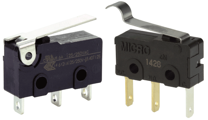
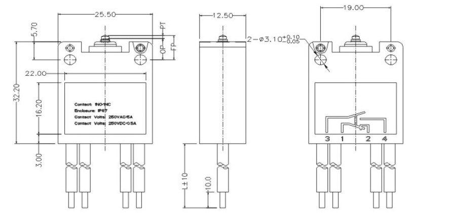
24 Jun 2020 — These are miniature switches and sub miniature switches. Although there are other types, the diagram above applies to all of them. In other ... Nov 08, 2017 · Micro Switch Tap Wiring Diagram. By Admin | November 8, 2017. 0 Comment. How to guide changing pressure water system ukcampsite co uk caravan repairs servicing and maintenance forum messages on off switch led rocker wiring diagrams oznium a complete push switches rs components china micro kw 12 electrical wire processing harness the custom ... Hey all! I'm trying to put together a handwired dactyl build with hotswap and RGBs in each switch using the [MxLEDBitPCB Amoeba](https://github.com/swanmatch/MxLEDBitPCB/blob/master/readme_en.md). I have my wiring finished and all my keys are working, but I'm having trouble with my RGBs.. Only the first 4 RGBs connected to my pro micro light up, they work perfectly as expected but I can't get any of the others after the 4th RGB to light up. I went out and bought a handy-dandy multimeter and d... A circuit diagram is included on the switch case labeling each of the terminals. The normal position corresponds to the switch plunger in its released position.2 pages
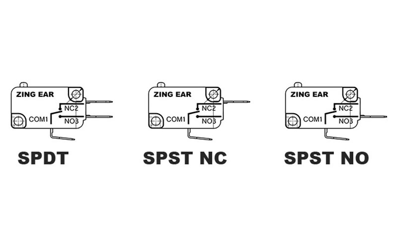
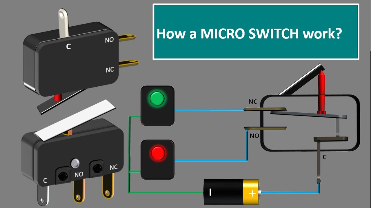
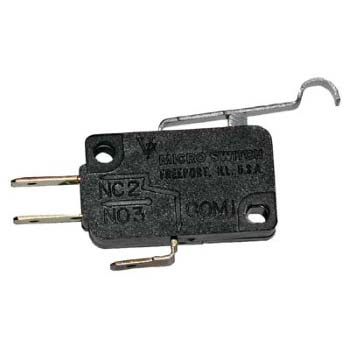
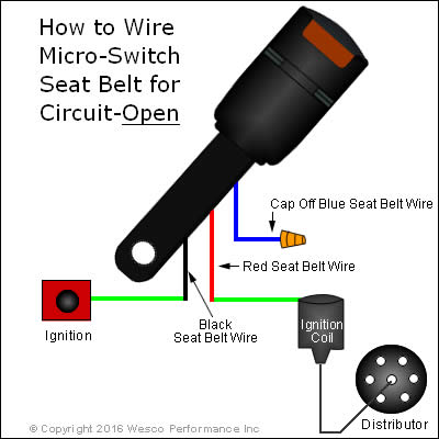
Hi everyone and thanks in advanced for the help. I'm in the process of putting together my first QMK and first custom keyboard, a Dactyl Manuform 5x7 based on Carbonfet's Fork found [here](https://github.com/carbonfet/dactyl-manuform). I did my initial wiring on one half (only wiring one half at a time and getting it working before doing both since I sort of anticipated this happening) according to how I understood [this diagram](https://raw.githubusercontent.com/abstracthat/dactyl-manuform/ma... Live Wires Allowed on the Micro Switch: The Micro Switch can have live wires connected to them, please refer to the wiring diagrams in section 2 below.12 pages 20 Aug 2018 — Micro switch are switches that need very less amount of force ... is the circuit connection showing the working of a micro switch when the ...3: NO (Normally Open)1: C (Common terminal)2: NC (Normally Close) I actually had this written down on a private post to myself but it keeps getting pushed down my own wall as I make new posts so I will post here presently. Just wanted to post where I'm at currently in my theories upon Idealism/nonduality. The idea is simply to get across certain philosophical ideas in a way which literally anybody would be able to understand. Because of this, throughout I will use "dualistic" terminology to explain "nonduality" largely. It doesn't matter what this means so m...

I'm about to attempt my first build using a [DIY Kit from Saberforge](https://www.etsy.com/listing/982978099/saber-forge-black-viper-mk2-full-diy?ref=shop_home_active_24&sca=1) and had a few questions about the wiring setup. Any help would be ***greatly*** appreciated! I'll be building a neopixel setup with the components included in the kit - relevant to my question, that means: (1) a single momentary AV switch, (2) a neopixel connector, (3) a seedling micro USB satellite board with 12mm a...

So I recently installed a new SKR Mini E3 v2 & BLTouch v3.1. The SKR Mini E3 seems to work perfectly, no issues there. The BLTouch, however, only works some of the time. It always lights up, the LEDs perform as expected (blue when extended, red/orange when stowed). When it works, I can generate a bed mesh in the Octoprint bed mesh visualizer plugin, I get predictable results, etc. I have printed a number of things successfully with it. The problem is that the BLTouch will sometimes fail to ...

Jul 15, 2020 · What is a micro switch diagram? This is a diagram which displays the various components of a micro switch in order to help you know how it is wired. If you are using a micro switch for the first time, it is important to know how the components have been structured.

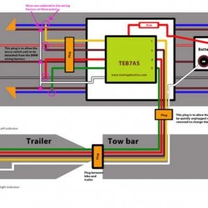
Hi can anybody tell me if and where there is the rear fog light relay? My rear fog light dont work and is kinda required for the yearly inspection. I checked the bulb, and there is no voltage. Fuse is fine and always on, 11+something volts. Tow bar, but no micro switch. Found a wiring diagram and there should be a relay, although it audibly clicks somewhere and the dash light goes on, Id like to check the relay. Cant find the damn thing and googling for it let me down too(!). Somewhere in the pa...

Hello! I am trying to set up some lighting for a spaceship kitbash I am making from some model kits. In the past I have used a battery pack for stuff like this, however I would like to use a wall plug for this one so it can be on for longer and because the unwieldy nature of the thing would make changing batteries difficult. In the imgur link below I have included a wiring diagram, which I hope is pretty accurate, to have something to reference to for what I am planning, as well as a picture of ...
So I finally started building some circuits that don't use PCBs, but instead use stripboard. The first I built was a fuzz face, so pretty easy to do, and it had full written instructions, so was easy to wire the off board components (switch, jacks, LED). Since I didn't have any issues, I bought the components to build an MXR Micro amp clone. I soldered all the on board components no problem, but now I am at the part where I wire this to the off board components, and that's what I can't figure o...

#**[Timestamps](https://imgur.com/a/Evk6gvg)** All prices include first-class shipping, CONUS only. I encourage asking for Priority for $5 more to avoid delays. I will consider messages in the order they come in, but timely bundle offers may get priority. Comment before messaging, no chat please.   |Boards/Keycaps|Details|Price|Available| |:--|:--|:-:|:-:| |~~R1 Grey Klippe T R4 + Boardwalk~~|~~Built with Boardwalk PCB and brass plate with MX housing NK Blueberries, 68g sprit spring...

Hello! So as I have stated in the title I have been trying to find a wiring diagram for a HyperX alloy FPS pro. I have a broken trace that connects the most left column of keys to the micro controller. I have been trying to figure out which pin it should connect to but I can't figure it out. Is there any way to figure it out without taking the switches out of the PCB?

MICRO SWITCH™ V-Basic Standard V15 Series Switches ... A circuit diagram is included on the switch case labeling each of the terminals.

See DIAGRAM Connect a Blue wire from the key switch to terminal 2 on the Golf/Street switch, and the Brown wire to terminal 1. May 18, · Connect them both to load on the micro switch. Wire you hot common/line/live , and neutral to micro. The micro is now acting as load for anything that was previously connected to the wall switch.


0 Response to "39 micro switch wiring diagram"
Post a Comment