38 fm transmitter block diagram
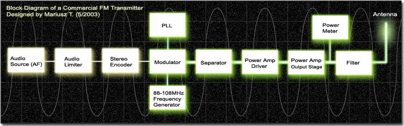
Block Diagram of FM Receiver with Explanation. Standard broadcast for FM is 88-108 MHz. The maximum permissible deviation is 200 KHz. In FM the intermediate frequency is 10.7 MHz. In FM the operating frequencies are much higher than that in AM. It additionally contain a de-emphasis and limiter circuit. The method of demodulation is totally ... Block diagram of an FM (frequency modulated) transmitter is given on Pic.2.4. Information being transferred, i.e. the modulating signal, is a signal from some LF source. it is being amplified in LF amplifier and then led into the HF oscillator, where the carrier signal is being created. The carrier is a HF voltage of constant amplitude, whose ...
Radio Transmitter Block Diagram. This block diagram of a radio transmitter in a communication system is very simple and basic. It is generalised for AM and FM types of modulation, and consists of four subsystems. Communication is the transfer of meaningful information from one location to another. We start with the conversion of sound waves in ...
Fm transmitter block diagram
FM Transmitters - Example • Assume fc drift 40 ppm/degree (40 x 5.1 = +/- 204Hz) ! 3672 Hz at the antenna; • Thus, following 5 degree temp. change ! freq. drift will be 18.36 KHz at the antenna! Block diagram of FM transmitter and receiver and its explanation. FM transmitter. Frequency Modulation is the process in which the frequency of the carrier signal is varied by the modulating signal while the amplitude remains constant. Using Reactance modulator direct method. Block diagram of a low level FM broadcast transmitter is shown in figure. The master oscillator generates the RF signal (carrier) required for modulation. Master oscillator is generally a well defined LC oscillator. The buffer amplifier is used to make the oscillator frequency free from the loading of the next stages.
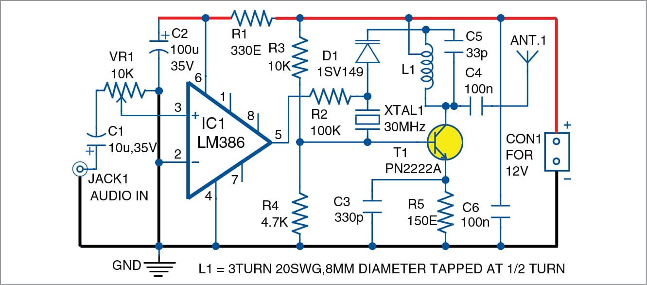
Fm transmitter block diagram. About Press Copyright Contact us Creators Advertise Developers Terms Privacy Policy & Safety How YouTube works Test new features Press Copyright Contact us Creators ... The writers of Block Diagram Of Fm Transmitter Circuit have made all reasonable attempts to offer latest and precise information and facts for the readers of this publication. The creators will not be held accountable for any unintentional flaws or omissions that may be found. FM Transmitter Circuit Principle: FM transmission is done by the process of audio pre amplification, modulation and then transmission. Here we have adapted the same formula by first amplifying the audio signal, generating a carrier signal using an oscillating and then modulating the carrier signal with the amplified audio signal. FM Transmitter Working Principle. The main function of an FM Transmitter Circuit is to transmit the sound using radio waves. So, at first, an FM Transmitter Circuit converts the sound or audio into radio wave then it transmit. You can see, in the block diagram of the FM Transmitter, the first block is the Microphone.
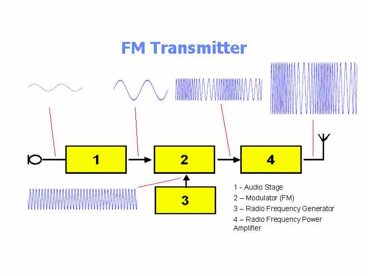
· The power amplification of the radio signal is carried out in the final stage of the block diagram. It makes the signal stronger so that it can be transmitted into the aerial. ... Frequency Modulated (FM) Transmitter. The diagram below shows the signals at various stages through an Frequency Modulated (FM) transmitter. F.M. Transmitter Tutorial - Block Diagrams - Electronics Circuit and Tutorials - Hobby Science Projects - The microphone converts sound pressure wave to electrical signals. These audio voltages are amplified by the audio amplifier. The amplified audio is used to control the deviation of the frequency controlled oscillator. FM Receiver Working Principle. To easily understand the working principle of FM Receiver, see the block diagram. The first block is the Antenna. The antenna is used to receive the radio signals and intercepted it. The next block is Radio Frequency Amplifier or RF amplifier. The RF amplifier is used to amplify the RF signal received by the antenna. Fm Transmitter Block Diagram And Explanation Of Each Block Pdf. The modulating signal is a signal from some LF source. The amplified signal is then applied to the mixer stage. 3672 Hz at the antenna. Figure shows the block diagram of a low-level AM transmitter. Using Reactance modulator direct method.
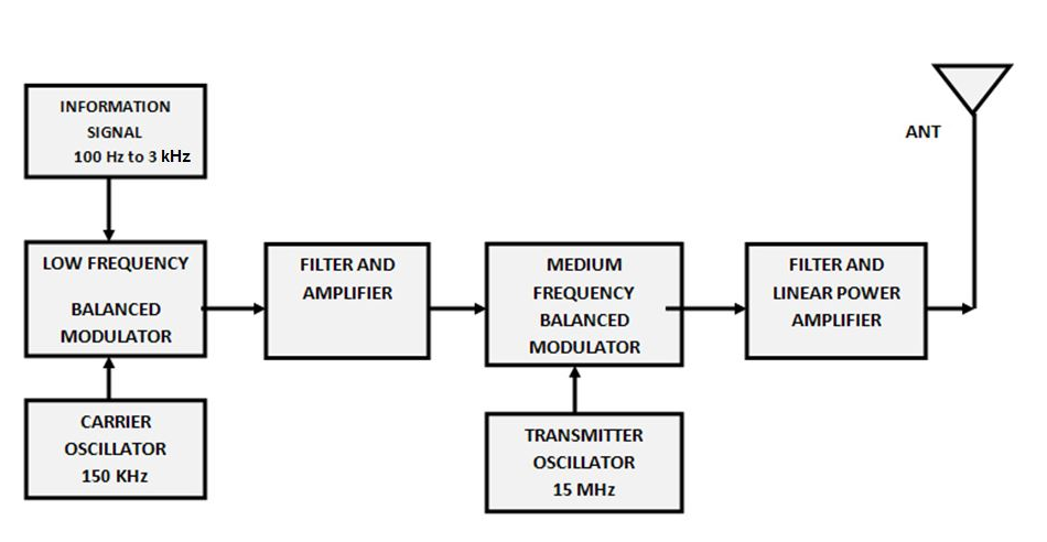
Block diagram of FM transmitter and receiver and its explanation. FM transmitter. Frequency Modulation is the process in which the frequency of the carrier signal is varied by the modulating signal while the amplitude remains constant. Using Reactance modulator direct method. The FM transmitter has three basic sections. Block Diagram of FM Transmitter. The following image shows the block diagram of the FM transmitter and the required components of the FM transmitter are; microphone, audio pre-amplifier, modulator, oscillator, RF- amplifier, and antenna. There are two frequencies in the FM signal, the first one is the carrier frequency and the other one is ... Armstrong FM Transmitter Block Diagram. The crystal-controlled carrier oscillator signal is directed to two circuits in parallel. This signal (usually a sine wave) is established as the reference past carrier signal and is assigned a value 0°. The circuit can also be used as a remote control transmitter. FM Demodulator using PLL - This is a good circuit of an FM demodulator with a schematic diagram, a design of FM demodulator, and working of PLL with block diagram. This will definitely be useful for your educational purposes. FM stereo demodulator using AN7415 - Stereo ...
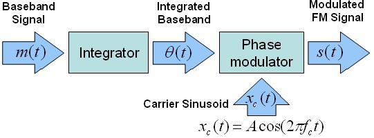
FM Transmitter Block Diagram. As the block diagram above illustrates, the integration of a message signal results in an equation for phase with respect to time. This equation is defined by the following equation: where k f is the frequency sensitivity. Again, the resulting modulation that must occur is phase modulation, which involves changing ...
FM Transmitter. FM transmitter is the whole unit, which takes the audio signal as an input and delivers FM wave to the antenna as an output to be transmitted. The block diagram of FM transmitter is shown in the following figure. The working of FM transmitter can be explained as follows.
A block diagram of a simple continuous wave (CW) transmitter is shown in Figure 6. The first block is the conventional crystal oscillator and then the final power amplifier. A power supply is provided for the oscillator and the final power amplifier. Figure 6. A block diagram representing various stages of a basic continuous wave radio transmitter.
FM Transmitter FM Modulation using VCO Block Diagram Chipset 4046 PLL 4046 VCO Characteristic Schematic PCB Layout Considerations PCB Layout Measured Results FM Receiver FM Demodulation using PLL Loop Filter Design VCO Design Block Diagram Chipset 4046 PLL Schematic PCB Layout Superheterodyne FM Receiver Block Diagram Chipset TDA7000 IF Filter Quadrature Demodulator IF Harmonic Distortion IF ...
A FM transmitter is a device that uses the principles of frequency modulation to broadcast sound supplied at its input. Typical FM transmitter design's usually follow the block diagram below; The signal strength of audio inputs into the transmitter is usually low therefore an amplifier is usually built to bring the signal level up.
• Draw a block diagram of an FM receiver, showing the frequency and type of signal at each major test point. • Explain the operation and alignment of Foster-Seeley/Ratio, PLL, and quadrature FM detector circuits. • Describe the features of noise-suppressing circuits in an FM receiver.
PDF File: Block Diagram Of Armstrong Fm Transmitter - PDF-10BDOAFT3 2/2 Block Diagram Of Armstrong Fm Transmitter e-Book Name : Block Diagram Of Armstrong Fm Transmitter - Read Block Diagram Of Armstrong Fm Transmitter PDF on your Android, iPhone, iPad or PC directly, the following PDF file is submitted in 11 Feb, 2021, Ebook ID PDF-10BDOAFT3.
Frequency modulated systems are operated usually at a frequency above 40 MHz. Frequency modulated broadcasting is done in television sound, mobile radio etc....
The FM Transmitter produces a range of VHF from 88 HZ to 108 MHZ. Block Diagram for FM transmitter circuit. Components required for FM transmitter circuit are modulator, oscillator, RF-Amplifier, Audio pre-amplifier, microphone and antenna. The Diagram shows the Block diagram for FM transmitter circuit.

The block diagram of NBFM modulator is shown in the following figure. Here, the integrator is used to integrate the modulating signal m ( t). The carrier signal A c cos. . ( 2 π f c t) is the phase shifted by − 90 0 to get A c sin. . ( 2 π f c t) with the help of − 90 0 phase shifter. The product modulator has two inputs ∫ m ( t ...
FM transmitter FM Transmitter Block Diagram Direct Method. Using Reactance modulator direct method. The FM transmitter has three basic sections. The exciter section contains the carrier oscillator, reactance modulator and the buffer amplifier.; The frequency multiplier section, which features several frequency multipliers.; The power output section, which includes a low-
Block diagram of a low level FM broadcast transmitter is shown in figure. The master oscillator generates the RF signal (carrier) required for modulation. Master oscillator is generally a well defined LC oscillator. The buffer amplifier is used to make the oscillator frequency free from the loading of the next stages.
Block diagram of FM transmitter and receiver and its explanation. FM transmitter. Frequency Modulation is the process in which the frequency of the carrier signal is varied by the modulating signal while the amplitude remains constant. Using Reactance modulator direct method.
FM Transmitters - Example • Assume fc drift 40 ppm/degree (40 x 5.1 = +/- 204Hz) ! 3672 Hz at the antenna; • Thus, following 5 degree temp. change ! freq. drift will be 18.36 KHz at the antenna!

0 Response to "38 fm transmitter block diagram"
Post a Comment