36 septic pump wiring diagram
Orenco Systems Control Panel Wiring Diagram Gallery. orenco systems control panel wiring diagram - Building wiring layouts show the approximate locations and also interconnections of receptacles, lighting, and also permanent electric solutions in a building. Adjoining wire courses could be revealed roughly, where certain receptacles or fixtures need to be on an usual circuit.
Septic Wiring Diagram Diy Diagrams Aerobic System Clipart Full Size 3966506 Pinclipart. Well Septic Systems Diagnostics Monticello Pump Services. Id 164 Steps In Constructing A Pressure Distribution Septic System. 220 Wiring Float Switch Setup For Septic Effluent Pump Green Tractor Talk.
pumped back to the septic tank by the waste pump. Clean water rises to the upper portion of the clarifier where it flows by gravity or is pumped out to the disposal area. ... electrical schematic and wiring diagram. If the delivery occurs before there is a place to install these components, they should be stored out of the elements and ...
Septic pump wiring diagram
Septic Tank Float Switch Installation 51 With Level Wiring Diagram 1024×919 On Pump 10 Septic Tank Float Switch . It reveals the elements of the circuit as simplified shapes and also the power as well as signal links between the tools. Sump pump wiring diagram. 3 backlit bilge rocker switch wiring diagram. Learn more about how our awesome ...
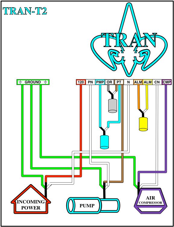
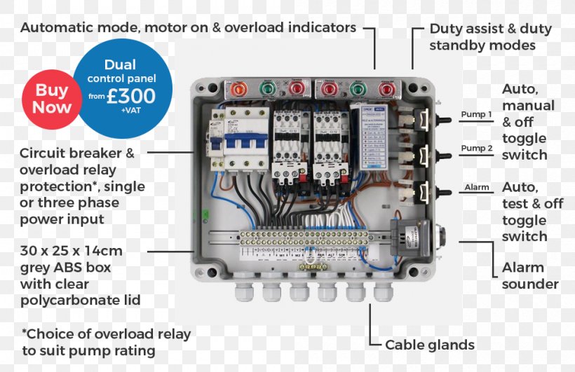
Connect the wires coming from the pumps to the pump terminals. Refer to the panel wiring diagram for the correct terminal connections for your system. 3. Connect the incoming power to the panel. Power to the panel must be appropriate to the control panel and pump motor (120 VAC, single-phase for a 120 VAC motor, 240 VAC single-phase for a 240
Assortment of clearstream septic system wiring diagram. A wiring diagram is a simplified conventional photographic depiction of an electrical circuit. It shows the components of the circuit as simplified shapes, and the power as well as signal links between the gadgets.
Septic pump wiring diagram.
475 Posts. #2 · Jan 18, 2011. Only show this user. John Brylinski said: I wired a duel float septic pump yesterday. The upper and lower float were factory wired to an "encapsulated" junction box within the tank, connecting to a 3 wire (no ground) with a male cap which exited the tank, into which the 220 volt cord end from the pump "piggy-backed".
Assortment of clearstream septic system wiring diagram. A wiring diagram is a streamlined standard pictorial representation of an electric circuit. It reveals the components of the circuit as streamlined shapes, as well as the power and also signal links in between the gadgets.
Chris shows you how to correctly wire the Double Float pump switches made by SJE Rhombus.The Double Float® pump switch consists of two floats and a splice tu...
wiring diagram of 2 float switch for two tanks wiring diagram of 3 motors diagram guitar fender also well and septic systems diagnostics. Where can I find a float switch wiring diagram? scenarios might include a Normally Open float switch turning on a pump to empty a tank (Control Schematic 2).
AWG wire, 25 LB-IN for 8 AWG wire, and 27 LB-IN for 6-4 AWG wire. 14. When power is applied to the control panel, the wires to the pump may be energized. Do not service the pump or any electrical wiring in the pump vault without disconnecting the power at the circuit breaker and the fuse. The pump vault area is a hazardous area,
septic pump float switch wiring diagram - What is a Wiring Diagram? A wiring diagram is an easy visual representation of the physical connections and physical layout associated with an electrical system or circuit.
Aerobic Septic System Alarm Alarm light or tone troubleshooting & repair. Installation instructions, wiring diagrams, etc. for septic system control and alarm . The diagram below references a V pump and wiring. Over 95% of aerobic septic systems use v rather than v.
Septic Tank Float Switch Wiring Diagram Fresh Champion Pump Wiring - Septic Tank Float Switch Wiring Diagram Wiring Diagram arrives with several easy to stick to Wiring Diagram Guidelines. It really is supposed to aid each of the typical person in developing a proper system. These instructions will probably be easy to comprehend and use.
Brandywine Septic Services Inc Pump Alarm 610 869 0443. Aerobic Septic System Alarm Faqs Q A On The Light Or Tone Controls. Float Switch Submersible Pump Sump Others Cable Dual Electrical Switches Png Pngwing. Septic Tank Float Switch Wiring Diagram Site Resource. 220 Wiring Float Switch Setup For Septic Effluent Pump Green Tractor Talk.
Septic Tank Alarm Wiring Diagram. Pump alarm aerobic septic system faqs q a on sewage pumping treatment how systems work king county duplex pumps sump high water alarms float pressure distribution tran t2 control panel tank switch wiring diagram spi bio with. Brandywine Septic Services Inc Pump Alarm 610 869 0443.
Assortment of septic pump wiring diagram. A wiring diagram is a simplified traditional photographic representation of an electric circuit. It shows the components of the circuit as simplified shapes, as well as the power as well as signal links between the tools.
Septic Pump Wiring Diagram from www.co.thurston.wa.us Print the electrical wiring diagram off in addition to use highlighters to trace the signal. When you make use of your finger or perhaps follow the circuit together with your eyes, it's easy to mistrace the circuit.
Network cartoon clipart - diagram, text, technology, transparent ...
Let s start with the most basic float switch. Wiring diagram of 2 float switch for two tanks wiring diagram of 3 motors diagram guitar fender also well and septic systems diagnostics. Switched outlet wiring diagram. 2 built in bilge running indicator. Each part ought to be set and connected with different parts in particular manner.
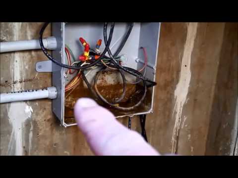
Bad float switch and wiring - onsite #1 - theplctech
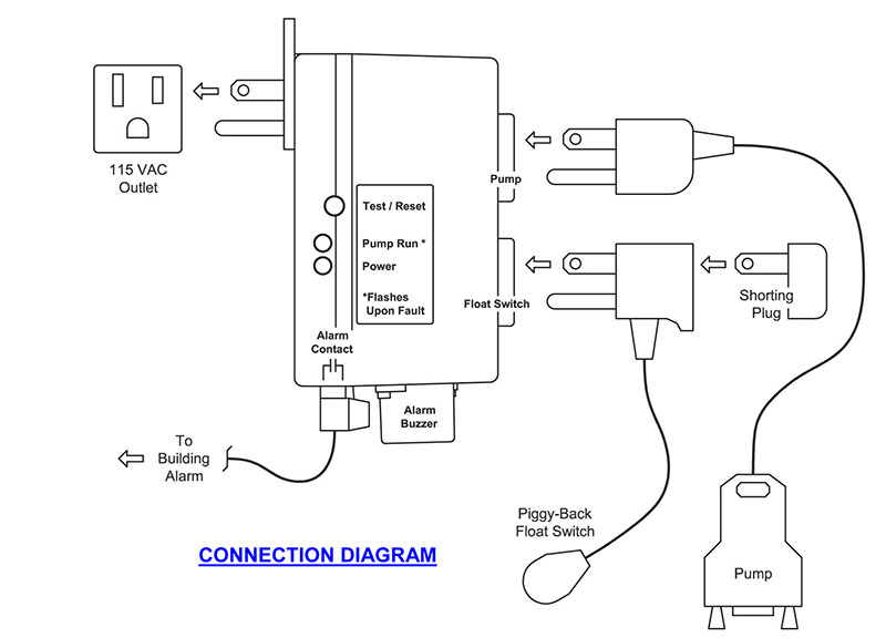
from the one used for the pump to ensure proper notification. 4. Now manually test the alarm by tilting the float switch up until you hear the alarm notification and you see the alarm light turn on. Mount the float switch using a proper float mounting clamp or cord weight. 5. Periodically test unit by touching the cover of the enclosure where ...
220 wiring/ float switch setup for septic effluent pump | green ...
Septic Pump Float Switch Wiring Diagram Download. septic pump float switch wiring diagram - A Novice s Overview of Circuit Diagrams A first take a look at a circuit representation might be complex, yet if you can check out a metro map, you can review schematics. The function coincides: obtaining from factor A to direct B. Literally,…

Septic control panels - wholesale septic supply | wholesale septic ...
Below is a simple diagram of a multi-chamber septic tank. Illustration 5. Multi-chamber septic tank. Septic tanks need to be subjected to regular pumping to empty it of all the sludge and scum that have accumulated. If not, the potential problems this brings are numerous, disgusting, and can be fatal for your entire system.
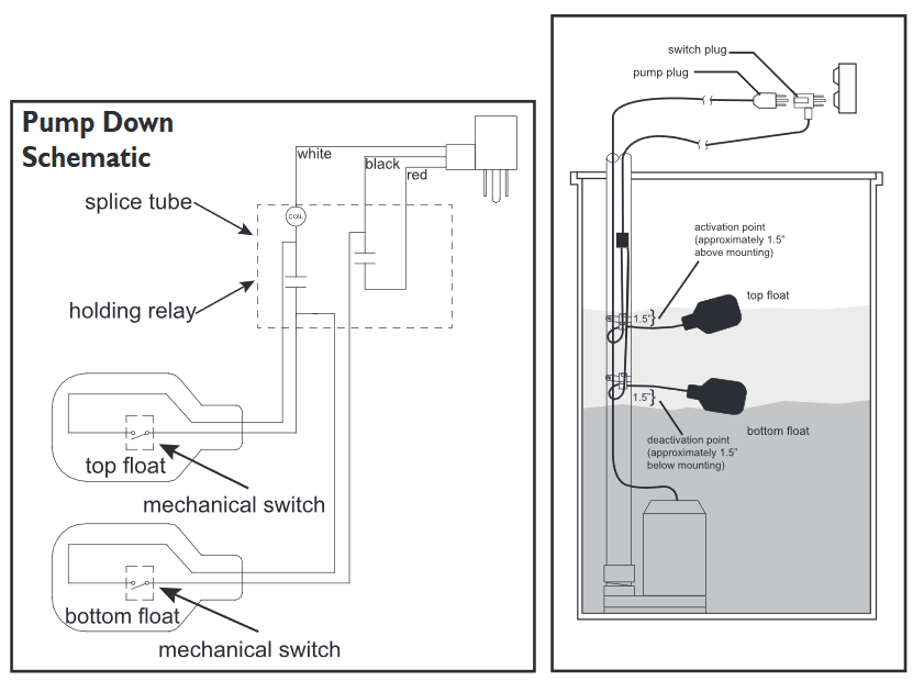
Double float® master - sje rhombus
Looking for ideas on wiring a septic pump. Im going to be running two 3/4 in PVC conduits from the house to the manhole. I was wanting to know if it is permissible by code to run one conduit. I want to put a 20amp circuit in the conduit with a 18/2 twisted shielded cable. What do you think...
Id-164: steps in constructing a pressure distribution septic system
Electrical wiring leads for the grinder pump and septic pump alarm; Electrical disconnect box for the grinder pump system; Drain inlet: 4" PVC tank inlet for connection to building drains served by the pump; Sewage pump tank vent. The sewage grinder tank must be vented either directly or through the inlet pipe and within 4 ft. of the tank to a ...

Exterior septic pump/alarm wiring - doityourself.com community forums
Pumps are used to move either raw sewage or septic tank effluent to different parts of the onsite sewage treatment system. Whether the pump handles raw sewage or septic tank ef-fluent, a pumping system consists of four parts: 1) a pump tank or sump; 2) the discharge assembly; 3) the controls; and 4) the pump.

Services-drain
Enclosure Box I Used: https://amzn.to/2PNw21mAudible Alarm with Float: https://amzn.to/2PKmnslSewage Septic Pump: https://amzn.to/2wlEuNeAlarm with Light and...
Piggyback required? can i direct wire? - ridgid forum | plumbing ...
How To Wire A Septic Tank Pump 92 with How To Wire A Septic Tank Pump Septic Tank Pump Alarm 75 with Septic Tank Pump Alarm We collect plenty of pictures about Septic Pump Wiring Diagram and finally we upload it on our website. Many good image inspirations on our internet are the best image selection for Septic Pump Wiring Diagram

Wiring septic systems: get the facts - griff electric
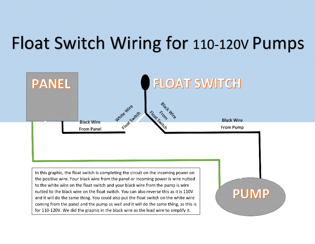
Submersible pumps use float switches to perform automatic operation. The float switch moves with the water level in the tank and this determines when the pump turns on and shuts off. In this article we will discuss the correct way to hard wire a float switch to a submersible pump in order to achieve automatic operation.
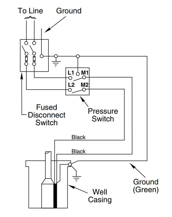
How to install and wire a well pump - well pump installation guide
I just had a sand mound septic system installed and need to complete the wiring. I have a 1 HP pump and a float alarm. The problem is the distance I have to go. The dosing tank is about 450' from the house and power source. I decided to put a sub panel at the dosing tank and was told that I needed to use 2-2-2-4 Aluminum SER wire.
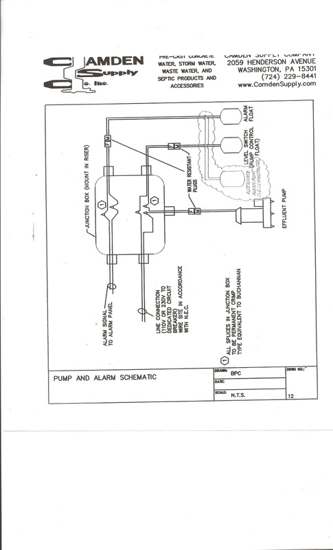
Pumps - camden supply company, inc.
Errant septic pump wiring troubleshoot | diy home improvement forum

Duplex septic & sewage pumps: buy & installation guide to duplex ...

12 awesome wiring diagram for 220 volt submersible pump ideas ...
Item # spex-1, sump and sewage pump exerciser® controllers for ...
Well & septic systems diagnostics - monticello well pump services

How to wire a septic tank pump & alarm system

Wiring for dual float switch system; well (high level on), cistern (lo
Wiring for a sewer pump | electrician talk

Septicpro-septic engineering-installation-maintenance in swanzey ...

Water pump wiring troubleshooting & repair pump wiring diagrams
Submersible pump wiring diagram control panel pumping station, png ...

Brandywine septic services, inc. -pump alarm - 610-869-0443

Wiring for dual float switch system; well (high level on), cistern (lo

Improve pump float switch reliability with a relay or contactor
How to wire a submersible pump - aerobic septic system
220 wiring/ float switch setup for septic effluent pump | green ...

We remodel a home and found the electrical bill 50 kwatts per day ...
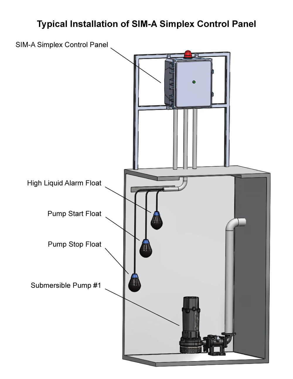
Sim-a three phase simplex pump control panel - see water inc.
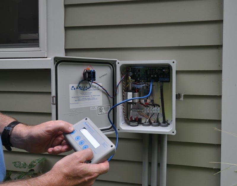
Aquaworx septic pump control box | infiltrator

Septic control panels - wholesale septic supply | wholesale septic ...

Float switch wiring diagram for water pump
How to install and wire a well pump - well pump installation guide

Septic wiring diagram diy diagrams - aerobic septic system wiring ...
0 Response to "36 septic pump wiring diagram"
Post a Comment