39 column interaction diagram example
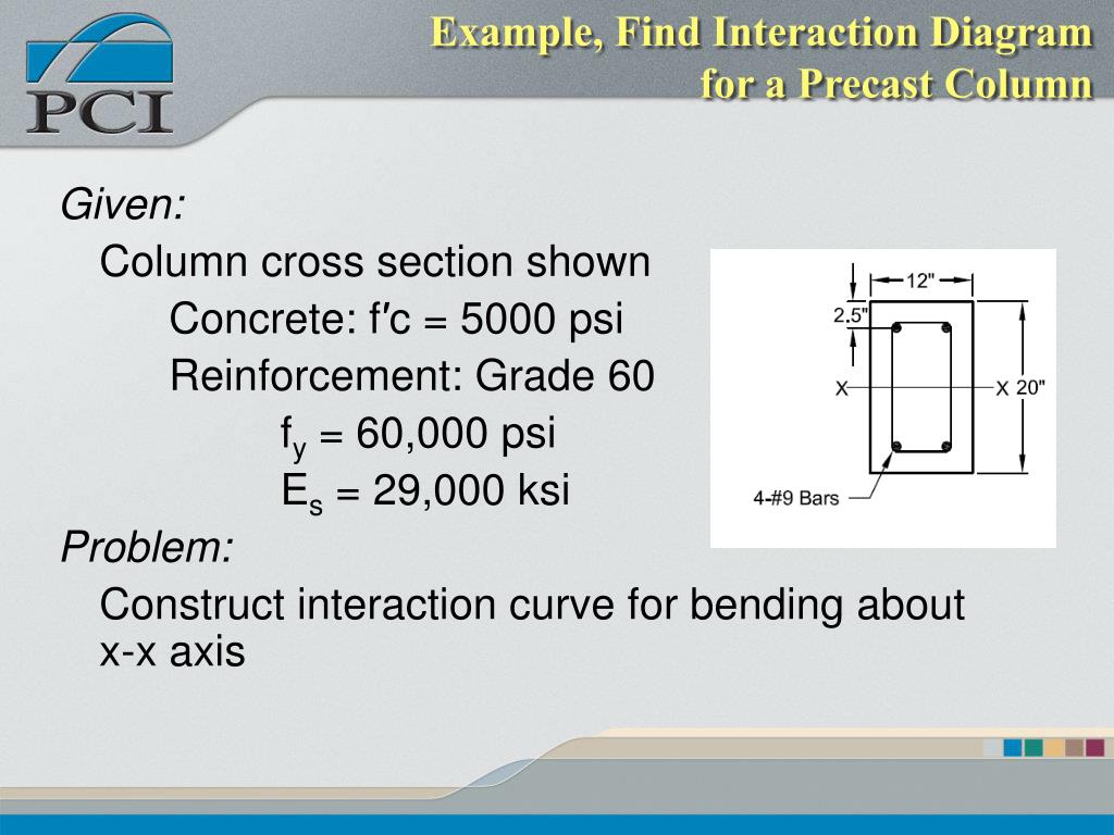
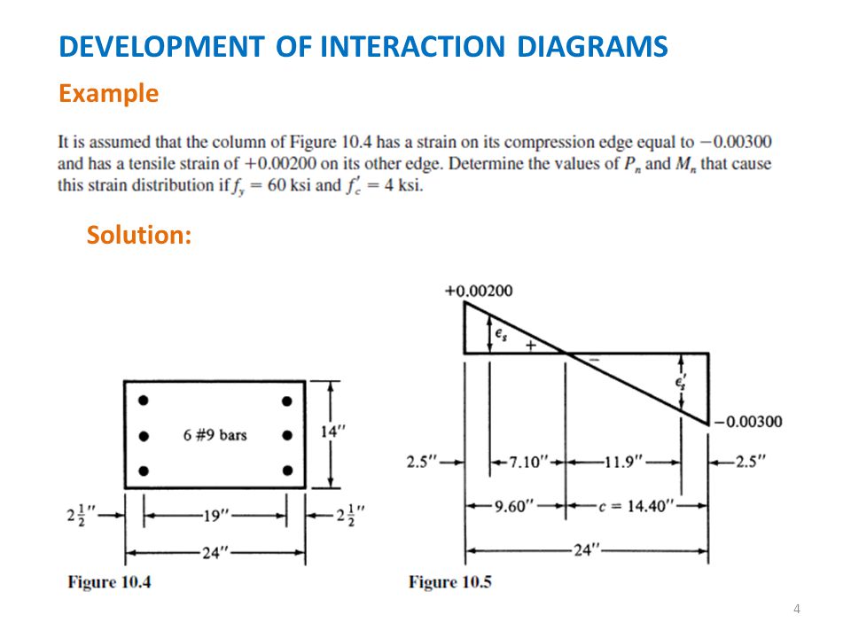
This problem shows the calculations and steps necessary to create an interaction diagram for a reinforced concrete column. This is helpful for creating home... Develop an interaction diagram for the square tied concrete column shown in the figure below about the x-axis. Determine seven control points on the interaction diagram and compare the calculated values in the Reference and with exact values from the complete interaction diagram generated by spColumn engineering software program from ...
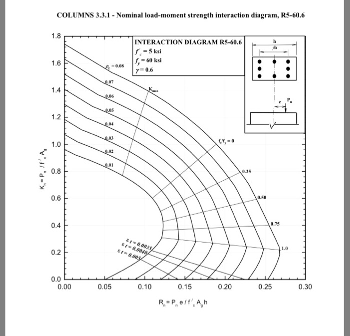
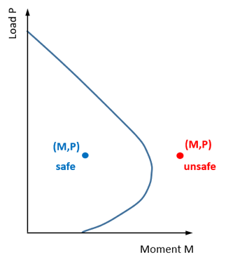
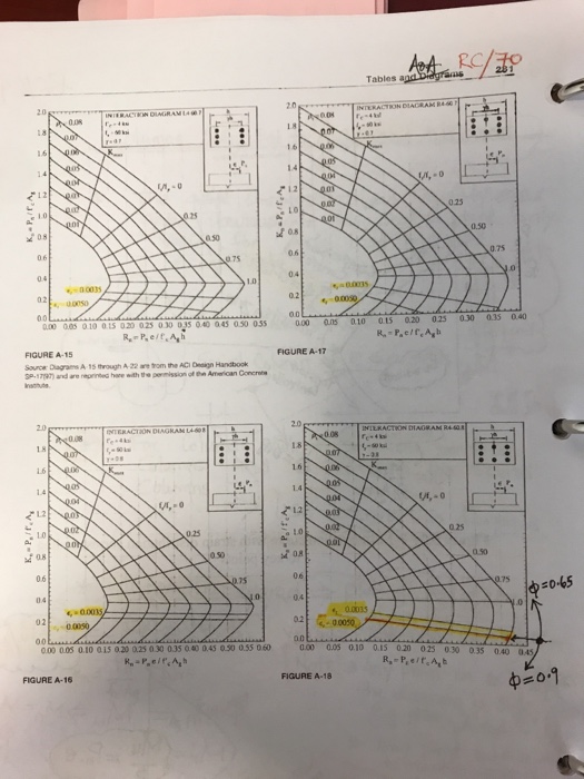
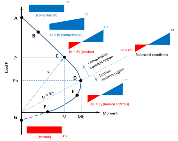
Interaction Diagram in a column is a graph which shows a plot for the axial load Pn that a column could carry versus its moment capacity, Mn. This diagram is very useful in analyzing the strength of column which varies according to its loads and moments. This can easily be interpreted as: the load combinations under any case that falls inside ...
Column interaction diagram example
Interaction diagram knowledge should have been an engineering “must-know” but sadly, due to technological advancements, and automatic program calculations, all we know is how to input the column properties and loads in the program.. then *voila*.. we’ve got an answer already. not even knowing where those values came from. Required: Interaction diagram in terms of capacity per foot Example – 8 in. CMU Bearing Wall Pure Moment: Nominal moment, / á Design moment, ϕ á Check to make sure stress block is in face shell # æ / á L # æ B ì @ F 5 6 º Þ Ù ä. Ù Ø ò ö / á0.90.924 · Ù ç Ù ç L0.840· Ù ç Ù ç = L º Þ Ù ä. Ù Ø ò L.. . Ñ ß : 4 ... Every point on the interaction diagram has a unique ratio of e P M n n = φ φ. Therefore, if e p M P M u u n n = = φ φ and φ Mn > Mu and φ Pn > Pu, then the column is adequate. Example Check a 16" x 16" column with 5 #9 bars in each face to see if it is adequate for Pu = 390k, M u = 220 k-ft. f’c = 3000 psi, fy = 60,000 psi. 1. Compute ...
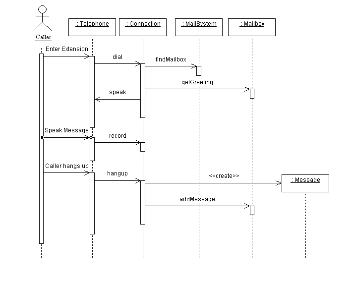
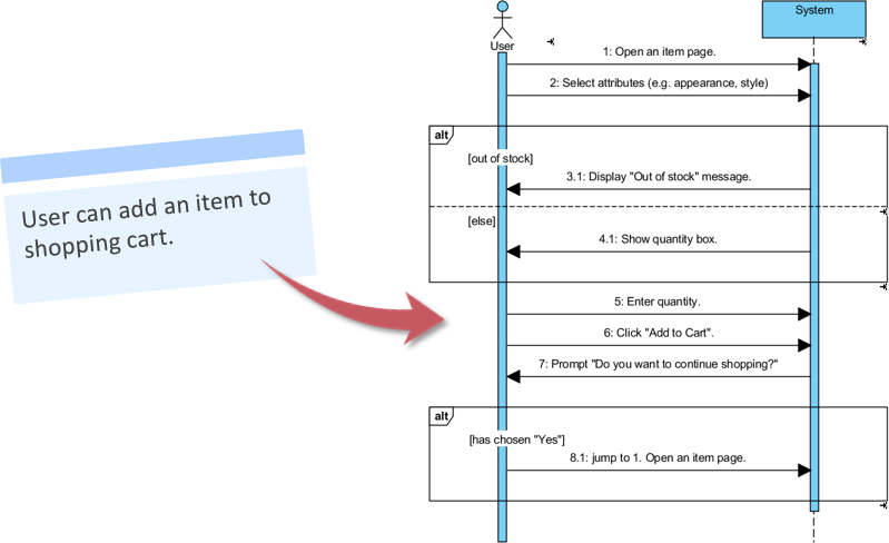
Column interaction diagram example. 4.17. Interaction Diagram of the Columns The interaction diagram of the columns was drawn to determine if the maximum axial load and moment exceeded the capacity of the column. The complete calculation to determine the important points of the interaction diagram is provided in Appendix XX. For all the columns of these two bridges, the maximum ... An interaction diagram provides us the context of an interaction between one or more lifelines in the system. In UML, the interaction diagrams are used for the following purposes: Interaction diagrams are used to observe the dynamic behavior of a system. Interaction diagram visualizes the communication and sequence of message passing in the system. Interaction Diagram - Tied Reinforced Concrete Column · 1. Pure Compression. · 2. Bar Stress Near Tension Face of Member Equal to Zero, ( εs = fs = 0 ) 4 · 3. Bar ... Figure 1: A sequence diagram. The second form of the interaction diagram is the collaboration diagram. Here the example objects are shown as icons. Again arrows indicate the messages sent in the use case. This time the sequence is indicated by a numbering scheme. Simple collaboration diagrams simply number the messages in sequence.
1 Apr 2021 — A column interaction diagram displays the combinations of the acceptable moment and axial capacities of a structural member. The column axial load - bending moment interaction diagrams included herein ... COLUMNS EXAMPLE 2 - For a specified reinforcement ratio, selection of a ...113 pages 2/20/2007 E702 Example Problems Interaction Diagrams for Concrete Columns D.D. Reynolds ,K.W. Kramer Calculate P n & M n by applying forces to free body diagram 79.95 kips 89.43 kips 489.60 kips Moment arms will be in inches, must convert to feet for desired Units. Point on curve for "Z" = .9 Figure 1.3: Column free body diagram for a "Z" of .9 ... Every point on the interaction diagram has a unique ratio of e P M n n = φ φ. Therefore, if e p M P M u u n n = = φ φ and φ Mn > Mu and φ Pn > Pu, then the column is adequate. Example Check a 16" x 16" column with 5 #9 bars in each face to see if it is adequate for Pu = 390k, M u = 220 k-ft. f’c = 3000 psi, fy = 60,000 psi. 1. Compute ...
Required: Interaction diagram in terms of capacity per foot Example – 8 in. CMU Bearing Wall Pure Moment: Nominal moment, / á Design moment, ϕ á Check to make sure stress block is in face shell # æ / á L # æ B ì @ F 5 6 º Þ Ù ä. Ù Ø ò ö / á0.90.924 · Ù ç Ù ç L0.840· Ù ç Ù ç = L º Þ Ù ä. Ù Ø ò L.. . Ñ ß : 4 ... Interaction diagram knowledge should have been an engineering “must-know” but sadly, due to technological advancements, and automatic program calculations, all we know is how to input the column properties and loads in the program.. then *voila*.. we’ve got an answer already. not even knowing where those values came from.

Arheologice Fustă Accent Calculate Ultimate Axial Load Of A Reinforced Concrete Column Muzeumdobranocek Com

Simplified Biaxial Column Interaction Charts Al Ansari 2019 Engineering Reports Wiley Online Library

Simplified Biaxial Column Interaction Charts Al Ansari 2019 Engineering Reports Wiley Online Library













0 Response to "39 column interaction diagram example"
Post a Comment