38 airplane free body diagram
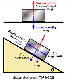
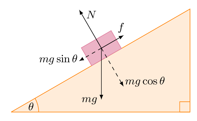
a) A box sits at rest on a rough 30 degree inclined plane. Draw free body diagram, showing all the forces acting on the box. b) How the diagram change if the box were sliding down the plane? c) How the diagram change if the box were sliding up the plane? (a) (b) (c) F N mg q F fr F N mg q F fr F N mg q F fr This physics video tutorial explains how to calculate the contact force between blocks using free body diagrams. It discusses how to determine the amount of...
-> Millions of them on google image search for "airplane free body diagram level flight". So anything wrong with NASA/Glenn's website is just the tip of the iceberg. Real/correct example: The hand sketch below shows an accurate free body diagram (FBD) for a sailplane in a steady state glide. The L/D is 60:1 (ASH 31 gets 56).
Airplane free body diagram
We can use the same isolation, or free-body diagram, of the figures above where now the point represents the Boeing 747, rather than you in an elevator, and the reaction force represents the lift force acting on the airplane, rather than the force acting on you at your interface with the elevator floor. From the requirement A free body diagram of the portion of the beam between the left end and plane a-a is shown in Fig. 3.3. A study of this section diagram reveals that a transverse force V r and a couple M r at the cut section and a force, R, (a reaction) at the left support are needed to maintain equilibrium. 2. Free-body diagrams for four situations are shown below. The net force is known for each situation. However, the magnitudes of a few of the individual forces are not known. Analyze each situation individually and determine the magnitude of the unknown forces. Then click the button to view the answers.
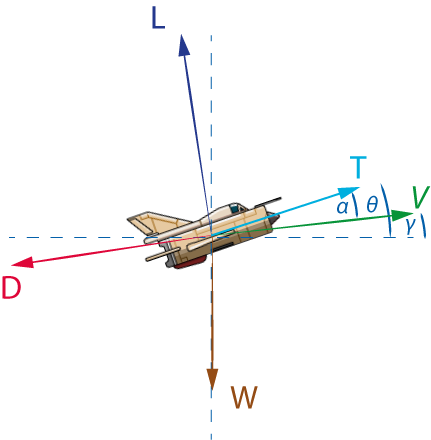
Airplane free body diagram. An airplane passes by overhead. The plane has a mass of 50,000 kg, is at an altitude of 10,000 meters and moves at a constant velocity of 150 m/sec. The altitude, velocity and direction of travel all are constant. Draw a free-body diagram of the airplane, including air drag. Identify as many forces as you can think of but do not try to ... A small aircraft may be designed for loads of positive 5G (wings pushed up relative to fuselage), but only negative 3G (wings pushed down). The well-known image of fighter aircraft quickly descending by steep banking first is an illustration of this difference in structural performance (as well as visibilty concerns). Two Blocks on an Inclined Plane. Construct the free-body diagram for object A and object B in (Figure). Strategy. We follow the four steps listed in ... As a wing moves through the air, the wing is inclined to the flight direction at some angle. The angle between the chord line and the flight direction is called the angle of attack and has a large effect on the lift generated by a wing. When an airplane takes off, the pilot applies as much thrust as possible to make the airplane roll along the runway.
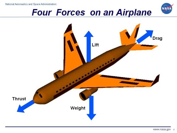
This page shows the parts of an airplane and their functions. Airplanes are transportation devices which are designed to move people and cargo from one place to another. Airplanes come in many different shapes and sizes depending on the mission of the aircraft. The airplane shown on this slide is a turbine-powered airliner which has been chosen as a representative aircraft. Computer drawing of an airliner showing vectors for lift, thrust, drag and weight. A force may be thought of as a push or pull in a specific direction. A force ... Sal draws a free body diagram for a box held stationary against a wall with a force at an angle theta.View more lessons or practice this subject at https://w... This physics video tutorial explains how to draw free body diagrams for different situations particular those that involve constant velocity ...
The figure below represents the free body diagram of the toy airplane. Free Body Diagram. The sum of forces acting along the y-axis is, {eq}T\cos \theta - mg = 0 {/eq} Download scientific diagram | Free body diagram of a fixed-wing aircraft during a pitching maneuver. from publication: A MAV that flies like an airplane and ... diagrams depict the variation of these quantities along the length of the member. Proceeding from one end of the member to the other, sections are passed. After each successive change in loading along the length of the member, a FBD (Free Body Diagram) is drawn to determine the equations express-ing the shear and bending mo- Which force on the airplane is larger in magnitude, the thrust or the drag? ... Sketch a free-body diagram showing the forces on the airplane in both the ...
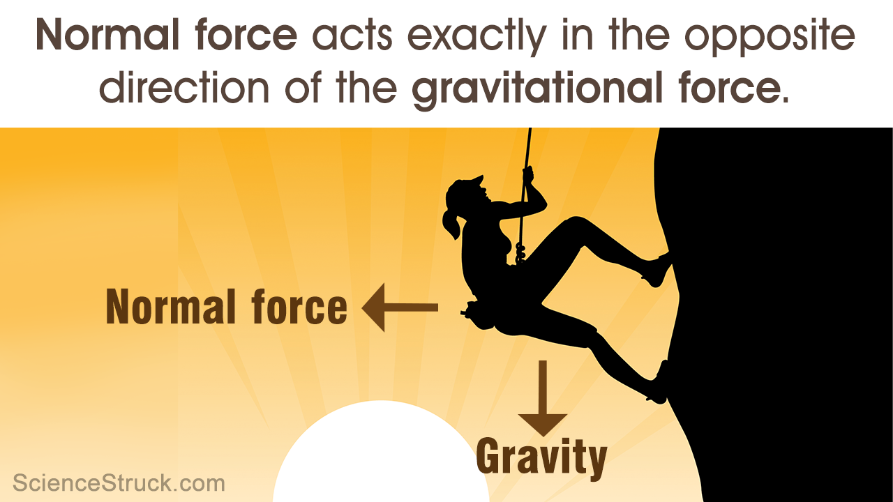
An Easy Guide To Understand Free Body Diagrams In Physics Science Struck
A general free-body diagram for steady level flight is presented in Figure 19-2. It is based on the dynamic diagram of Section 18.2.1, General two-dimensional free-body diagram for an aircraft, and Equations (18-1) and (18-2) (18-1) (18-2).

A Pilot Of Mass M In A Jet Aircraft Executes A Loop The Loop As Shown
Free-body diagrams are very useful in analyzing forces acting on a system and are employed extensively in the study and application of Newton's laws of motion. A more quantitative definition of force can be based on some standard force, just as distance is measured in units relative to a standard distance.
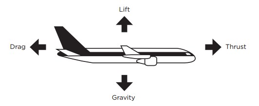
Four Forces Of Flight Science World
A free-body diagram for the car on the banked turn is shown at left. The banking angle between the road and the horizontal is (theta). The normal force, N, has been resolved into horizontal and vertical components (the blue vectors). In the vertical direction there is no acceleration, and: so: In the horizontal direction: Since F net = F ...

Loads Acting On Aircraft Aerospace Engineering Blogaerospace Engineering Blog
Airplane Free-body diagram!! Homework Statement A plane with mass of 1090 kg is flying straight and level at an altitude of 1100 meters & a constant velocity of 200 kg/hr (55.55m/sec).Assuming that the acceleration due to gravity is 10 m/sec^2, the force on the plane due to gravity is 10900 Newtons.Since the plane is in level flight, the net force in the y direction is 0 & the lifting force ...

Sph4c
A heavy plane, or a plane meant to carry heavy payloads, requires more lift than a light plane. It may also require more thrust to accelerate on the ground. On small aircraft the location of weight is also important. A small plane must be appropriately "balanced" for flight, for too much weight in the back or front can render the plane unstable.
Free Body Diagrams Images Stock Photos Vectors Shutterstock
This video introduces and explains both free body diagrams and objects on an inclined plane for A Level Physics.A free body diagram is used ...
Silo Tips
This Dissertation is brought to you for free and open access by UWM Digital Commons. It has been accepted for inclusion in Theses and Dissertations ... Figure 5.3: Free Body Diagram of the Piston ..... 96 Figure 5.4: Shaking Force in the x and y Directions (800 rpm) ..... 99 Figure 5.5: Shaking Force in the x and ...

Example Problem
An airplane wing free body diagram illustrating forces acting on the wing. Keywords plane, planes, Aerodynamic of Aeroplane Wing, Airplane Wing Free Body Diagram, Aerodynamic Wing Free Body Diagram. Galleries Air Transportation. Source. H. Barber The Aeroplane Speaks (New York, NY: Robert M. McBride & Co, 1917)
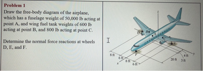
Solved Problem 1 Draw The Free Body Diagram Of The Airplane Chegg Com
A free body diagram consists of a diagrammatic representation of a single body or a subsystem of bodies isolated from its surroundings showing all the forces acting on it. In physics and engineering , a free body diagram (force diagram, [1] or FBD) is a graphical illustration used to visualize the applied forces , moments , and resulting ...

Choose The Force Diagram Freebody Diagram That Best Represents The Forces Acting On The Ball The Brainly Com
7.2 Plane Trusses Method of Joints 1. Draw a free-body diagram of the entire structure and determine the reactions (if r = 3). 2. Draw free-body diagrams for all members (assume tensile forces in all members) and all joints. 3. Set up the equilibrium equations for each joint and solve them one joint at a time, begin with those that

Free Body Diagram Of The Aircraft During Level Flight Download Scientific Diagram
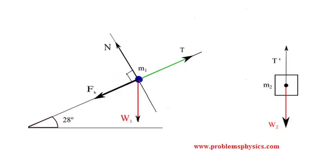
The free-body diagram is also shown, with the forces split into components parallel and perpendicular to the inclined plane. Because there is no acceleration, any coordinate system is fine - a system parallel and perpendicular to the ramp is pretty convenient, though, because two of the forces are along those directions.

Dylan Stapp
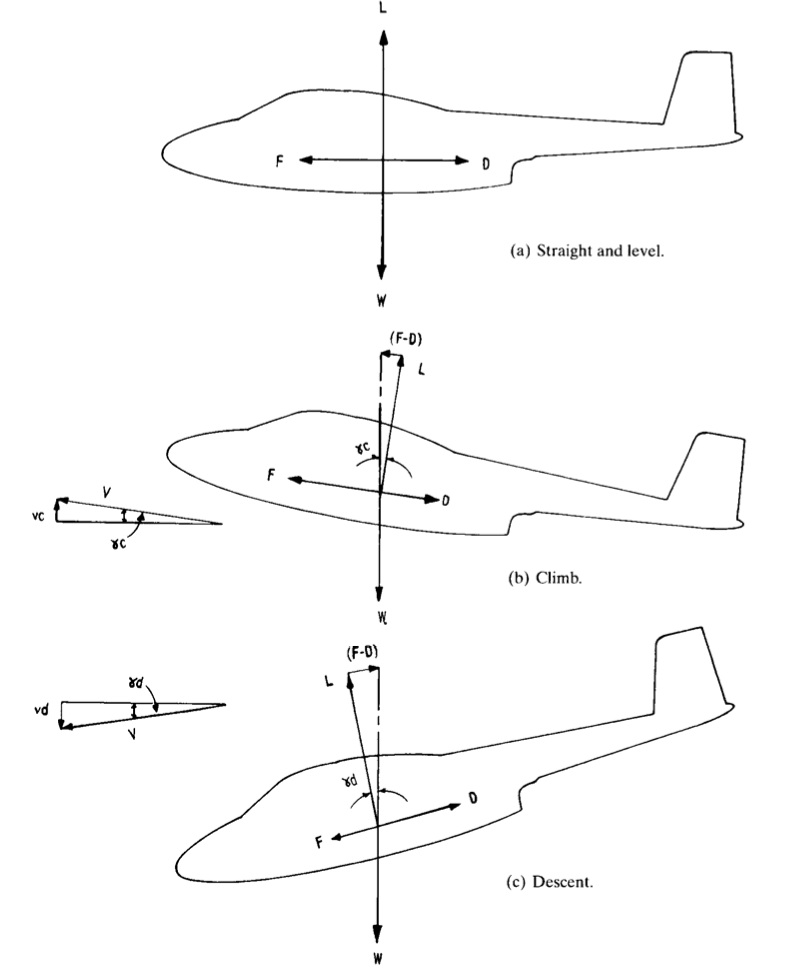
4) drag-essentially a friction force, acting opposite the direction of motion. For an airplane which is neither climbing nor descending, the free- body diagram ...

Free Body Diagram An Overview Sciencedirect Topics
Figure 1: A simple plane pendulum (left) and a double pendulum (right). Also shown are free body diagrams for the forces on each mass. 2 Newton's equations The double pendulum consists of two masses m 1 and m 2, connected by rigid weightless rods of length l 1 and l 2, subject to gravity forces, and constrained by the hinges in the rods to ...

Airplane Forces By Daniel Sanchez Uribe Infographic
The figure below shows a free-body diagram of this. Where: g is the acceleration due to gravity, which is 9.8 m/s 2 m is his mass D is the drag force acting upwards W is the force of gravity pulling him down v is the speed at which he falls v t is the constant (terminal) speed he reaches when D = W It is easy to understand why his speed ...
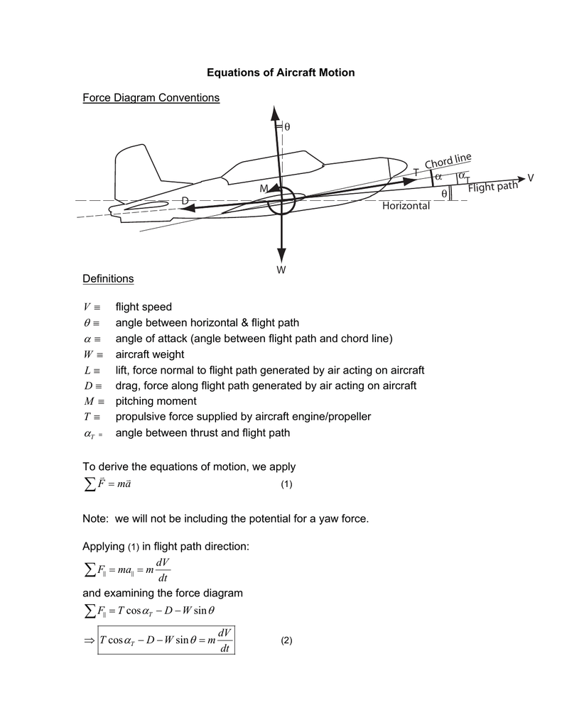
Equations Of Aircraft Motion Force Diagram Conventions Definitions
A free-body diagram can be drawn very simply, with squares and arrows, or you can make it much more complex. The only requirement is that you or someone else looking at it should be able to understand what the diagram is telling. A free-body diagram (FBD) is a representation of a certain object showing all of the external forces that acts on it.
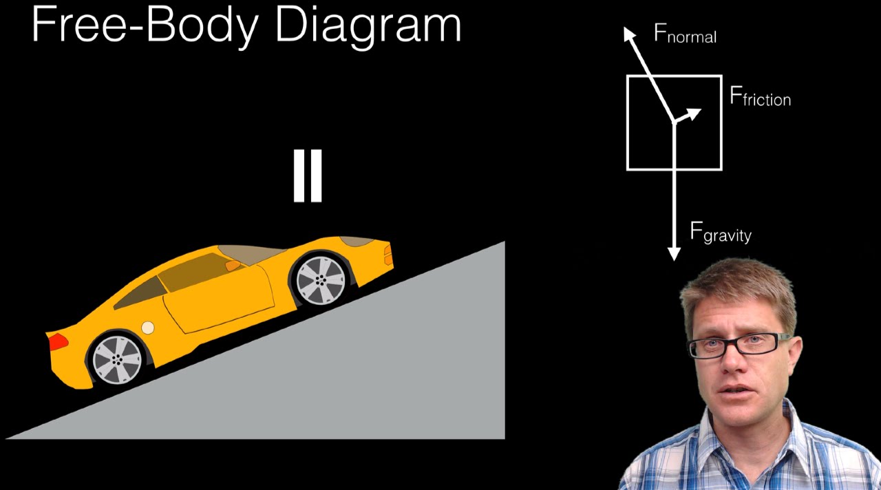
Free Body Diagrams Youtube
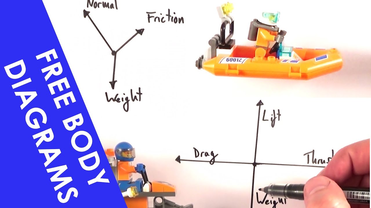
Drawing Free-Body Diagrams. Free-body diagrams are diagrams used to show the relative magnitude and direction of all forces acting upon an object in a given situation. A free-body diagram is a special example of the vector diagrams that were discussed in an earlier unit. These diagrams will be used throughout our study of physics.
Free Body Diagram Of An Inclined Plane In Tikz Tikzblog
Always draw good, detailed "free body diagrams"! ... Airplane pilots are in this situation as they pull out of a dive. The ratio of this "apparent weight" to real weight may be described as the apparent effect of gravity or may be described as "g-forces". "g-forces" of six or seven -- meaning an apparent weight of six or seven times one's real ...

Aircraft And Treadmills Simple Scientist
2. Free-body diagrams for four situations are shown below. The net force is known for each situation. However, the magnitudes of a few of the individual forces are not known. Analyze each situation individually and determine the magnitude of the unknown forces. Then click the button to view the answers.
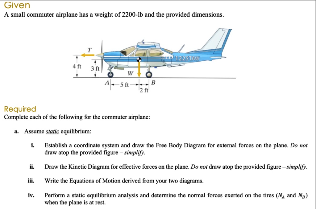
Solved Given A Small Commuter Airplane Has A Weight Of 2200 Lb And The Provided Dimensions 122staw 4 Ft 3 Ft W A 5 Fti B 12 Ft Required Complete Each Of The Following For
A free body diagram of the portion of the beam between the left end and plane a-a is shown in Fig. 3.3. A study of this section diagram reveals that a transverse force V r and a couple M r at the cut section and a force, R, (a reaction) at the left support are needed to maintain equilibrium.
Free Body Diagrams Tutorials With Examples And Explanations
We can use the same isolation, or free-body diagram, of the figures above where now the point represents the Boeing 747, rather than you in an elevator, and the reaction force represents the lift force acting on the airplane, rather than the force acting on you at your interface with the elevator floor. From the requirement
Loads Acting On Aircraft Aerospace Engineering Blogaerospace Engineering Blog
Forces On An Airplane

Equilibrium At Constant Velocity

M 2 Friction And The Inclined Plane
Modeling Part 2 Equations Of Motion
Forces In A Climb
Aapt Scitation Org

Simplified Free Body Diagram Of The Aircraft Download Scientific Diagram
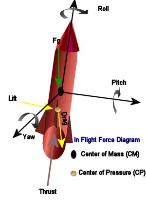
In Flight

Free Body Diagram An Overview Sciencedirect Topics
Free Body Diagrams And Objects On An Inclined Plane A Level Physics Youtube

Physics Reference The Force Diagram Shows An Aircraft Accelerating At The Instant Shown The Velocity Of The Aircraft Is 40 M S 1

2 Force Diagrams During A Typical Climb Download Scientific Diagram

Answered Which Of The Following Is The Correct Bartleby

What Are The Forces Present In A Coordinated Turn Aviation Stack Exchange

Aeronautics Aeronaut Hub

External Flow Lift And Drag Nexus Wiki
Solved Draw The Free Body Diagram Of The Wing Of The Chegg Com
0 Response to "38 airplane free body diagram"
Post a Comment