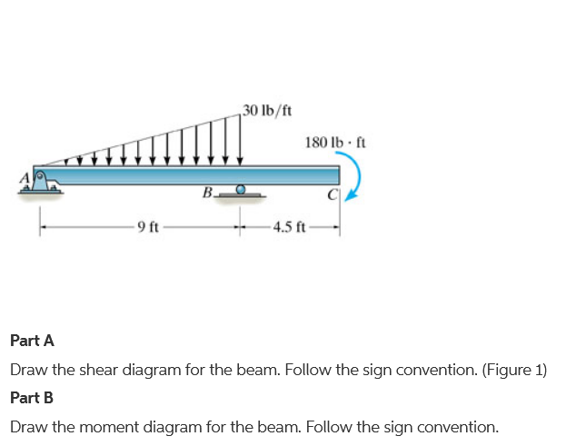
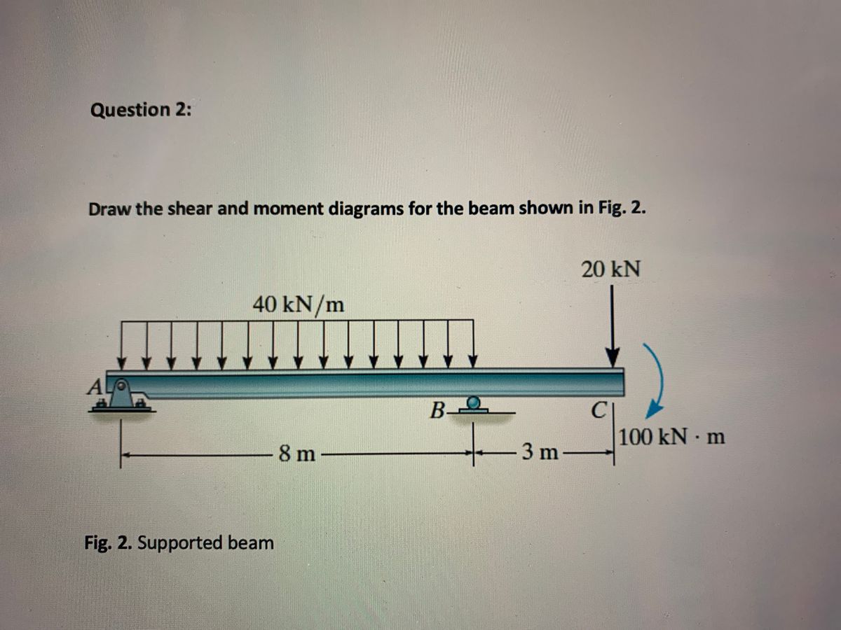
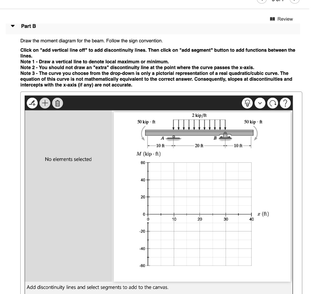
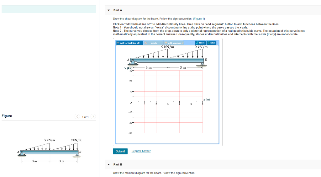
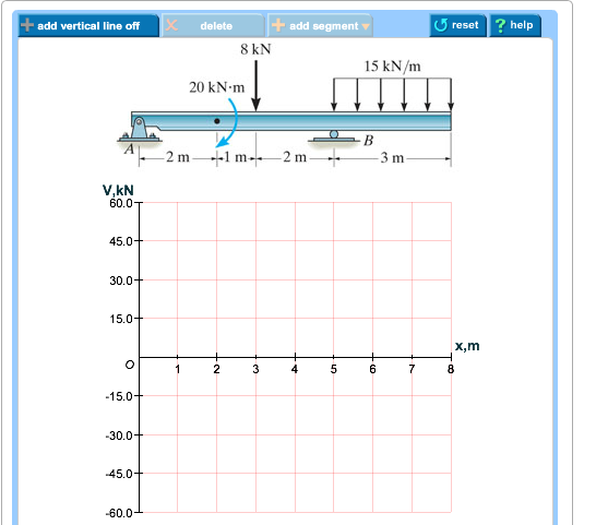
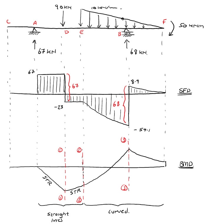
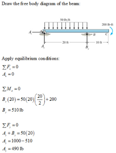
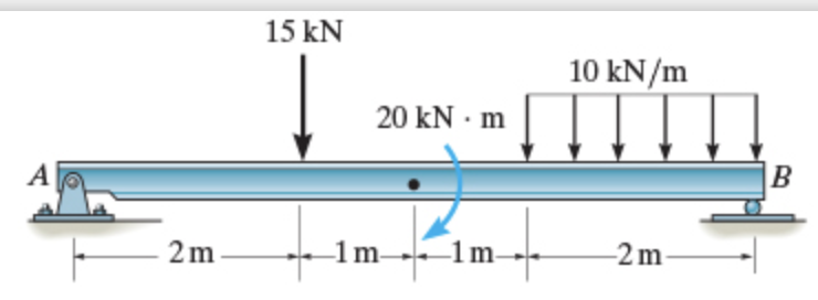
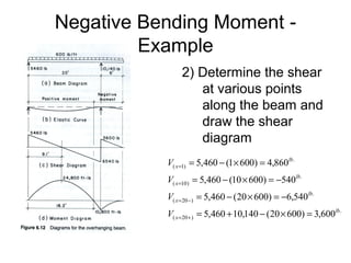
42 draw the shear diagram for the beam.
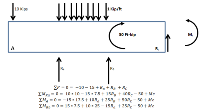
Answered: Draw the shear diagram for the beam.… | bartleby Solution for Draw the shear diagram for the beam. Draw the moment diagram for the beam. close. Start your trial now! First week only $4.99! arrow_forward learn. write. tutor. study resourcesexpand_more. Study Resources ... Draw the shear diagram for the beam. Draw the moment diagram for the beam. Answered: Draw the shear and moment diagram of… | bartleby Transcribed Image Text: Draw the shear and moment diagram of the given beam. Consider support A is roller and B is pin. 4 kN 2 kN 2 kN/m 1m 1 m.
draw the moment diagram for the cantilevered beam ... Draw the shear and moment diagrams for the beam. Solved Draw The Shear Force Diagram And Ben. This can be accessed under any of our Paid Accounts which also includes a full structural analysis software. Advanced Physics questions and answers. 7-48 Draw the shear and moment diagrams for the cantilevered beam. Indicate the degree of each curve.
Draw the shear diagram for the beam.
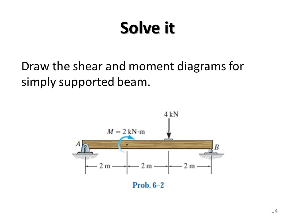
How to Draw Shear Force & Bending Moment Diagram | Simply ... Draw shear force and bending moment diagram of simply supported beam carrying point load. As shown in figure below. Solution First find reactions of simply supported beam. Both of the reactions will be equal. Since, beam is symmetrical. i.e., R1 = R2 = W/2 = 1000 kg. Now find value of shear force at point A, B and C. Draw The Shear And Moment Diagrams For The Overhang Beam. Shear and Moment Diagrams Procedure for analysis - the following is a procedure for constructing the shear and moment diagrams for a beam. The change in the shear force is equal to the area under the distributed loading. If the distributed loading is a curve of degree n, the shear will be a curve of degree n+1. Can you draw the shear force and bending moment diagrams ... Answer (1 of 2): EDIT 2020-09-14 Without explaining all the calculus to prove it, a simple rule of thumb is: 1. the change in shear = -(area under the load curve (w)) 2. slope of the V curve = -(w) 3. slope of the M curve = V 4. the change in M = area under the V curve. Here's how I got my numb...
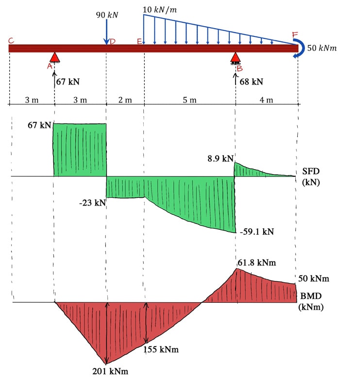
Draw the shear diagram for the beam.. Draw the shear and moment diagrams for the beam, and ... Mechanics of Materials - Instructor Solutions Manual [EXP-4667] Draw the shear and moment diagrams for the beam, and determine the shear and moment throughout the beam as functions of x. Step-by-Step Report Solution Verified Solution Scan the QR Code To Continue Browsing on Your mobile Device. How to Calculate and Draw Shear and Bending Moment Diagrams These instructions will help you to calculate and draw shear and bending moment diagram, as well as draw the resulting deflection. Knowing how to calculate and draw these diagrams are important for any engineer that deals with any type of structure because it is critical to know where large amounts of loads and bending are taking place on a beam so that you can make sure your structure can ... Draw the shear and moment diagrams for the overhang beam ... Shear Diagram. The shear of −2 kN −2kN at end A of the beam is plotted at x = 0 x = 0, Fig. 6-16 c . The slopes are determined from the loading and from this the shear diagram is constructed, as indicated in the figure. In particular, notice the positive jump of 10 kN 10kN at x = 4 m x = 4m due to the force B_y By , as indicated in the figure. The Ultimate Guide to Shear and Moment Diagrams ... 4.0 Building Shear and Moment Diagrams 4.1 Finding the location of the maximum bending moment 5.0 Drawing Shear Force and Bending Moment Diagrams - An Example 5.1 Video Tutorial 5.2 Calculating the support reactions 5.3 Drawing the shear force diagram 5.4 Drawing the bending moment diagram 6.0 Relating Loading, Shear Force and Bending Moment
Draw the shear and moment diagrams for the beam shown in ... Draw the shear and moment diagrams for the beam shown in Fig. 4-13a. | Holooly.com Support Reactions. The reactions are calculated and indicated on the free-body diagram. Shear Diagram. The values of the shear at the end points A A \left (V_ {A}=+100 \mathrm {lb}\right) (V A = +100 lb) and B\left (V_ {B}=-500 \mathrm {lb}\right) B(V B (Book Solutions) Draw the Shear and Moment Diagrams for ... Draw the shear and moment diagrams for the beam. Indicate values at the supports and at the points where a change in load occurs. Solution: Check Other Problems' Solutions : Book Solutions for Structural Analysis by R C Hibbeler. As per the Conditions of Static Equilibrium of the Structural Element: ∑Fy = 0, ∑Fx = 0, and ∑M = 0 Solved Review Draw the shear diagram for this beam. Begin ... Review Draw the shear diagram for this beam. Begin by placing the lines of discontinuity. Place the appropriate function between the lines of discontinuity, ensuring the endpoints have the correct values. Note - Make sure you place only one vertical line at places that require a vertical line. Shear Force Diagram - How to Draw a SFD - mechGuru Here are simple five steps applicable for drawing almost all types of shear force diagram correctly (Refer the following typical example in connection with the below steps): 1. Draw a horizontal line to represent the beam and divide the line by putting points at the following locations: - At the reaction locations. 2.
PDF Chapter 4 Shear and Moment In Beams - ncyu.edu.tw 4.3 Shear- Moment Equations and Shear-Moment Diagrams The determination of the internal force system acting at a given section of a beam : draw a free-body diagram that expose these forces and then compute the forces using equilibrium equations. The goal of the beam analysis -determine the shear force V and How to Draw Shear Diagrams | ReviewCivilPE The beam is 20ft long divided into 5 foot sections. Shear diagrams always begin and end at zero, with all of the forces on the member shown in between. Starting from the left, the first force you come across is the 10 lb downward force at the left end. This is the first point of data, draw a line from zero to negative 10. Draw the Shear and Moment diagrams for the beam- With ... Draw the Shear and Moment diagrams for the beam 1) Calculate the shear force and bending moment for the beam subjected to concentrated load as shown in the figure. Also, draw the shear force diagram (SFD) and the bending moment diagram (BMD). Solution; Free body diagram of the given figure, Taking moment about point B, R Ay x 4 - 20 x 2 = 0 Answered: Draw the shear diagram for the beam… | bartleby Draw the shear diagram for the beam Click on "add vertical line ofr to add discontinuity lines. Then click on "add segment" button to add functions between the lines. Note 1- Make sure you place only one vertical line at places that require a vertical line.
Shear Force and bending moment diagram - ExtruDesign Steps to draw Shear force and Bending moment diagrams. In SFD and BMD diagrams Shear force or Bending moment represents the ordinates, and the Length of the beam represents the abscissa. Consider the left or the right portion of the section. Add the forces (including reactions) normal to the beam on the one of the portion.
Solved Draw the shear diagram for the beam. Draw the ... Draw the shear diagram for the beam. Draw the moment diagram for the beam. Who are the experts? Experts are tested by Chegg as specialists in their subject area. We review their content and use your feedback to keep the quality high. Transcribed image text: Draw the shear diagram for the beam. Draw the moment diagram for the beam.
[Solved] For the beam and loading shown draw the shear and ... Are you looking for the beam and loading shown draw the shear and bending moment diagrams? then you are at the right place on the web. Beams come with different kinds and different types of loading on them. Hence, Submit your questio n and get solved within a few hours.
PDF Draw the shear force and bending moment diagrams for the ... (Cambridge)7.12Draw the bending moment and shearing force diagrams for the beam shown. The beam is supported horizontally by the strut DE, hinged at one end to a wall, and at the other end to the projection CD which is firmly fixed at right angles to AB. The beam is freely hinged to the wall at B. The masses of the beam and strut can be neglected.
Solved Draw the shear diagram for the beam. Assume that w ... Draw the shear diagram for the beam. Assume that w 0 =10kip/ft , and L=18ft Draw the moment diagram for the; Question: Draw the shear diagram for the beam. Assume that w 0 =10kip/ft , and L=18ft Draw the moment diagram for the
Can you draw the shear force and bending moment diagrams ... Answer (1 of 2): EDIT 2020-09-14 Without explaining all the calculus to prove it, a simple rule of thumb is: 1. the change in shear = -(area under the load curve (w)) 2. slope of the V curve = -(w) 3. slope of the M curve = V 4. the change in M = area under the V curve. Here's how I got my numb...
Draw The Shear And Moment Diagrams For The Overhang Beam. Shear and Moment Diagrams Procedure for analysis - the following is a procedure for constructing the shear and moment diagrams for a beam. The change in the shear force is equal to the area under the distributed loading. If the distributed loading is a curve of degree n, the shear will be a curve of degree n+1.
How to Draw Shear Force & Bending Moment Diagram | Simply ... Draw shear force and bending moment diagram of simply supported beam carrying point load. As shown in figure below. Solution First find reactions of simply supported beam. Both of the reactions will be equal. Since, beam is symmetrical. i.e., R1 = R2 = W/2 = 1000 kg. Now find value of shear force at point A, B and C.














0 Response to "42 draw the shear diagram for the beam."
Post a Comment