40 delco remy voltage regulator wiring diagram
Delco Remy Alternator Wiring Diagram - Wiring Diagram Delco Alternator Wiring Diagram — Daytonva150 - Delco Remy Alternator Wiring Diagram Wiring Diagram includes many in depth illustrations that display the link of varied things. It includes guidelines and diagrams for various varieties of wiring strategies and other items like lights, windows, etc. Delco Remy External Voltage Regulator Wiring Diagram ... Delco 10Si Alternator Wiring Diagram - delco 10si alternator wiring diagram, Every electrical structure consists of various different pieces. Each component ought to be set and connected with other parts in specific way. If not, the structure will not function as it should be.
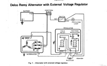
Voltage Regulator Wiring Diagram Manual - U Wiring Or alternator controllervoltage regulator output will be 05 to 2V less than the voltage at A B D or E. Delco remy regulator wiring diagram alternator with external catalog 10 dn 2018 05 ebook databases for a 1970 chevy voltage wire ford c10 battery troubleshooting gm 4 mechman regulation 101 the 1947 present 68 camaro internal correct dodge ...
Delco remy voltage regulator wiring diagram
Externally Regulated Alternator Wiring - Wiring Diagrams The easiest way to identify that the alternator is internally or externally regulated is to look in the engine bay for the presence of a voltage. Delco-Remy 10DN Externally Regulated Alternator Wiring Diagram GM Externally Regulated Alternator to Voltage Regulator Wiring. Wiring instructions for the. Alternator Wiring Diagrams and Information - BRIANESSER.COM VOLTAGE REGULATOR The regulator has two inputs and one output. The inputs are the field current supply and the control voltage input, and the output is the field current to the rotor. The regulator uses the control voltage input to control the amount of field current input that is allow to pass through to the rotor winding. Wiring Prestolite Diagram Regulator Voltage [3QVS16] Search: Prestolite Voltage Regulator Wiring Diagram. About Diagram Regulator Prestolite Voltage Wiring
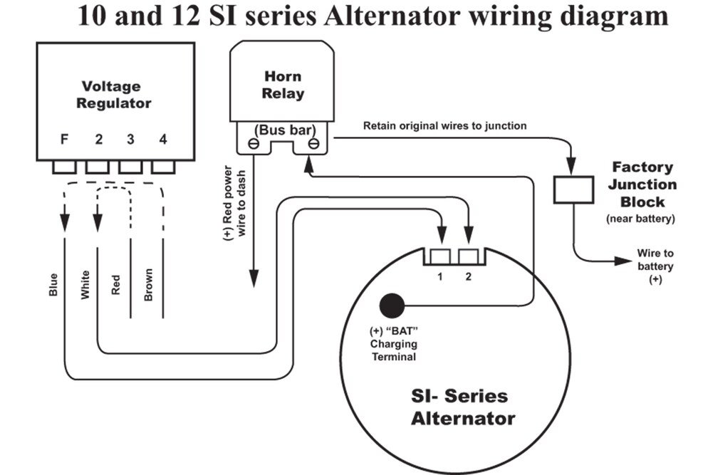
Delco remy voltage regulator wiring diagram. Delco Remy Alternator Wiring Diagram - Wirings Diagram There are just two things that will be present in any Delco Remy Alternator Wiring Diagram. The first element is symbol that indicate electrical element in the circuit. A circuit is usually composed by many components. The other thing that you will see a circuit diagram could be traces. Wiring Diagram For Voltage Regulator Delco 10si Delco Remy ture a solid state regulator that is mounted inside the stator a.c. voltages to a d.c. voltage values of R2, R3, R5, TR1 and and then back to the battery. Also, Figure 5-Typical SI wiring diagram showing internal circuits.The 1 wire regulator comes with a dust plug for the #1 & #2 terminals. Delco Diagram Remy 28si Wiring [2W6UMD] Search: Delco Remy 28si Wiring Diagram. About Diagram Remy Delco Wiring 28si How to Wire a GM External Regulated 10DN Alternator Delco-Remy 10DN Externally Regulated Alternator Wiring Diagram GM Externally Regulated Alternator to Voltage Regulator Wiring Wiring instructions for the early GM Delco Remy external regulated alternator. How to wire an external voltage regulator on a GM vehicle.
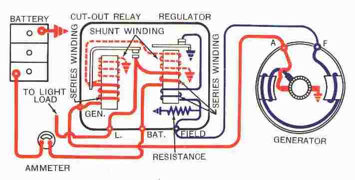
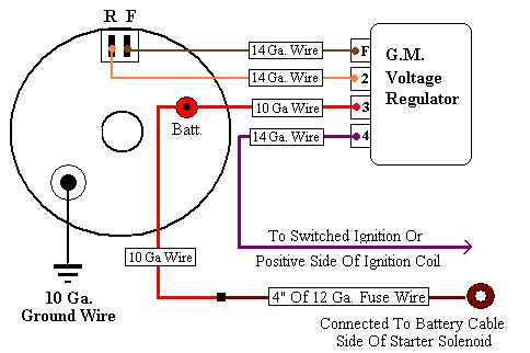
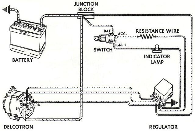
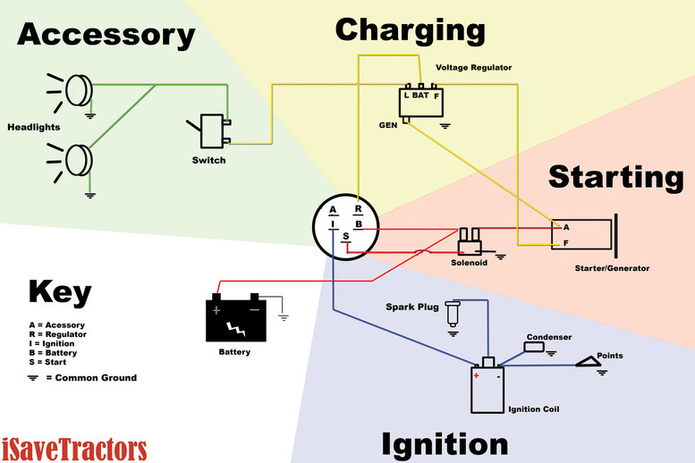
delco remy voltage regulator wiring diagram/page/4 ... Find your delco remy voltage regulator wiring diagram/page/4 here for delco remy voltage regulator wiring diagram/page/4 and you can print out. Search for delco remy voltage regulator wiring diagram/page/4 here and subscribe to this site delco remy voltage regulator wiring diagram/page/4 read more! PDF Delco-Remy Service Bulletin 1R-116 - ruiter.ca An examination of the wiring diagram, Figure 3, will show that regulation begins at the point where the shunt windings are connected to the series circuit. Any small resistance added to the circuit between the generator and this point will simply be offset by a rise in generator voltage without affecting the out— put shown at the ammeter. Wiring Diagram for Garden Tractors with a Delco Remy ... The below diagram also shows our 5 prong, 3 position ignition switch, and our 4 prong mechanical voltage regulator. Note: You can either operate your accessories such as your headlights off of the "L" terminal of the voltage regulator as shown, or run headlights from the "A" terminal on the ignition switch. delco remy voltage regulator wiring diagram/page/3 ... Find your delco remy voltage regulator wiring diagram/page/3 here for delco remy voltage regulator wiring diagram/page/3 and you can print out. Search for delco remy voltage regulator wiring diagram/page/3 here and subscribe to this site delco remy voltage regulator wiring diagram/page/3 read more!
How to Wire a GM Delco type CS130 series alternator Delco-Remy CS-130 Internally Regulated Alternator Wiring Diagram GM CS130 Series Internal Regulated Alternator Wiring Wiring instructions for the GM Delco Remy internally regulated CS130 alternator. The GM Delco-Remy cs130 alternator was used on GM vehicles from about 1986-1996. 1995 -1998 was a transitional period for the cs-130. Wiring Diagram External Voltage Regulator [9T41W8] Search: External Voltage Regulator Wiring Diagram. About Diagram External Wiring Regulator Voltage delco remy voltage regulator wiring diagram/page/103 ... Find your delco remy voltage regulator wiring diagram/page/103 here for delco remy voltage regulator wiring diagram/page/103 and you can print out. Search for delco remy voltage regulator wiring diagram/page/103 here and subscribe to this site delco remy voltage regulator wiring diagram/page/103 read more! Instruction Sheets for Starters & Alternators | Delco Remy Download How-To instructions for replacement parts on Delco Remy Starters & Alternators.
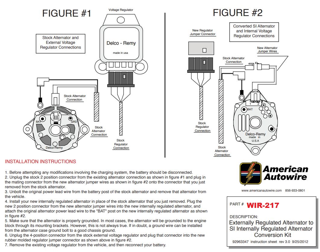
1967 - 1972 Camaro Alternator Conversion Wiring Harness Kit, SI
delco remy voltage regulator wiring diagram | Wirings Diagram Find your delco remy voltage regulator wiring diagram here for delco remy voltage regulator wiring diagram and you can print out. Search for delco remy voltage regulator wiring diagram here and subscribe to this site delco remy voltage regulator wiring diagram read more!
Nissan/Datsun Z Car Voltage Regulator Conversion
Remy 20182 Wiring Diagram - schematron.org Remy 20182 Wiring Diagram. 19.10.2018. 19.10.2018. 6 Comments. on Remy 20182 Wiring Diagram. Delco Remy Alternator Wire Diagram 2 file PDF Book only if you are registered here. . Wire with 2 Groove Remy Premium. Delco Remy. Remy Remanufactured Alternator Seller & Payment Information Seller Alternator Voltage regulator 3 Wire Connector Harness ...

Does anyone know anything about 20dn alternators? - The 1947 ...
Instruction Sheet 14JL16 REV4 - Delco Remy If it has a ground lead, place it on ground terminal and tighten nut to 5.0-8.5 Nm (44-75 lb in).Delco Remy strongly recommends use of a ground lead. 6. Place output lead on output terminal and tighten nut to 7.5-10.0 Nm (66-88 lb in). DO NOT OVER TIGHTEN OUTPUT FIGURE 3] 10SI ALTERNATOR TERMINAL NUT! FAN ON 11SI VOLTAGE REGULATOR OPENING (MAY

Home Made Power Generator - Perma Pak Food Storage
Fabulous Delco Remy Alternator Wiring Diagram 4 Wire Whole ... Search for delco remy alternator wiring diagram 4 wire here and subscribe to this site delco remy alternator wiring diagram 4 wire read more. Delco remy alternator wiring diagram 4 wire . This particular model 10si used in the 1970s and early 80s is the one you ll find on the generation of gm cars most often used in demolition derbies.
Testing Delco 10DN external voltage regulator : Other ...
Delco Remy Voltage Regulator Wiring | Wiring Diagram ... Delco Remy Alternator Wiring Diagram - delco remy 10si alternator wiring diagram, delco remy 22si alternator wiring diagram, delco remy 24si alternator wiring diagram, Every electric structure is composed of various distinct components. Each component should be placed and connected with different parts in particular way. Otherwise, the structure will not work as it should be.

Alternator Voltage Regulation 101 (with Wiring Diagrams) - In ...
Delco Remy Alternator Wiring Diagram - easywiring This diagram shows how to wire a delco gm internally regulated 3 wire alternator this particular model 10si used in the 1970s and early 80s is the one you ll find on the generation of gm cars most often used in demolition derbies. Replacing a 20dn 30dn 41 dn and d c. Replacing delco remy 10si 11si 12si or bosch k1 alternators with 11si alternator.
Delco Remy 1R-111 Current-Voltage Regulator Colour Bulletin ...
Wiring Prestolite Diagram Regulator Voltage [3QVS16] Search: Prestolite Voltage Regulator Wiring Diagram. About Diagram Regulator Prestolite Voltage Wiring
Technical - Delco remy 12v HELP | The H.A.M.B.
Alternator Wiring Diagrams and Information - BRIANESSER.COM VOLTAGE REGULATOR The regulator has two inputs and one output. The inputs are the field current supply and the control voltage input, and the output is the field current to the rotor. The regulator uses the control voltage input to control the amount of field current input that is allow to pass through to the rotor winding.
Regulator/Rectifier Conversion
Externally Regulated Alternator Wiring - Wiring Diagrams The easiest way to identify that the alternator is internally or externally regulated is to look in the engine bay for the presence of a voltage. Delco-Remy 10DN Externally Regulated Alternator Wiring Diagram GM Externally Regulated Alternator to Voltage Regulator Wiring. Wiring instructions for the.
need to know correct voltage regulator | Garden Tractor Forums
Alternator + voltage regulator help please ...

Alternator wiring - conversion from external to internal ...
Voltage regulator - Studebaker Drivers Club Forum
Untitled
CONVERTED?? Extra wires? - Ford Truck Enthusiasts Forums
CSOBeech - Inside Bonanza & Baron Voltage Regulators
Bob's Studebaker Resource and Information Portal (1970 Delco ...

12V DC Wiring Bible - Part 2 -Tech Article by BillaVista ...
Alternator wiring question? | Off Roading Forums
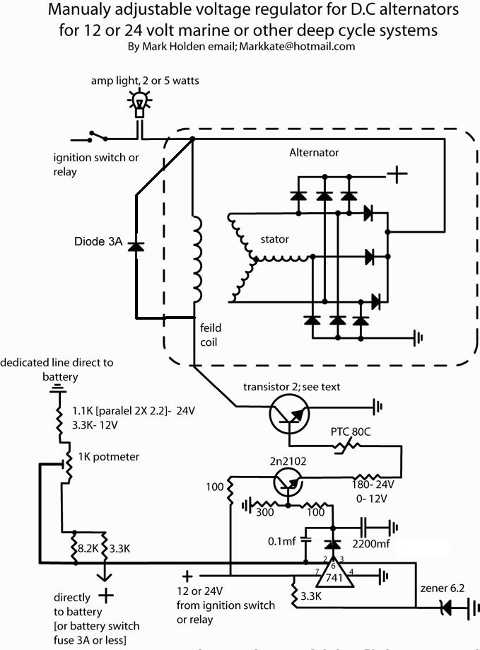
Self build adjustable alternator controler

Delco Two wire alternator connection issue - E-Type - Jag ...
Delco 10 DN Regulator Wiring (2012-05-05) - Tractor Shed
Vire 7 Starter Generator Circuit Diagrams

Regulator DELCO-REMY 10503805
Schematic of experimental setup used to study ignition of ...
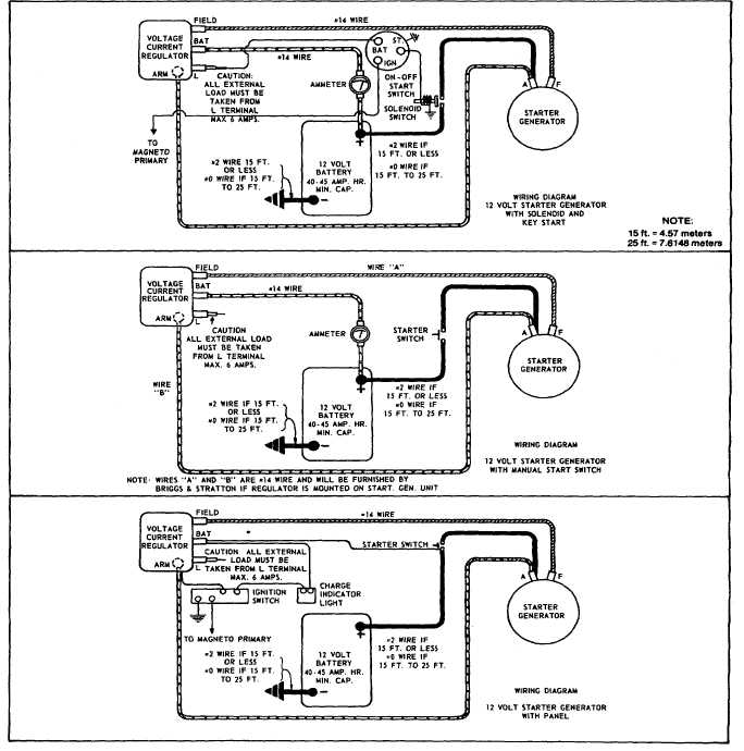
STARTER-GENERATOR WIRING DIAGRAM
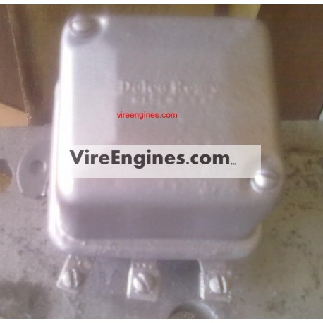
CHARGE REGULATOR ( DELCO dynastart) - Refurbished - VIRE
/stories/2018/07/43253.jpg)
Voltage Regulators | Hemmings
Testing Delco 10DN external voltage regulator : Other ...

Panhead and Flathead site ::

Voltage Regulator Problem - Technical - Antique Automobile ...

Starter Generator wiring - Talking Tractors - Simple trACtors

Polarizing Your Delco Remy Generator on a Farmall A,B,C,SA ...

Replaced Alternator on 1066 - Technical IH Talk - Red Power ...
Wiring Diagram for Garden Tractors with a Delco Remy Starter ...

67-72 Camaro Voltage Regulator Conversion Plug Converts ...

Delco Remy Generator Wiring Circuit | Delco, Electrical ...
36SI™ High Output Brushless Alternator | Delco Remy

Alternator Issue
3 Wire Alternator | Hot Rod Forum
0 Response to "40 delco remy voltage regulator wiring diagram"
Post a Comment