39 emon dmon wiring diagram
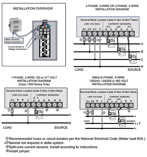
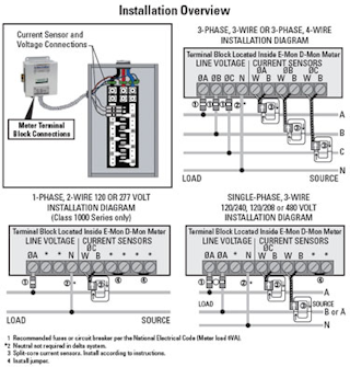
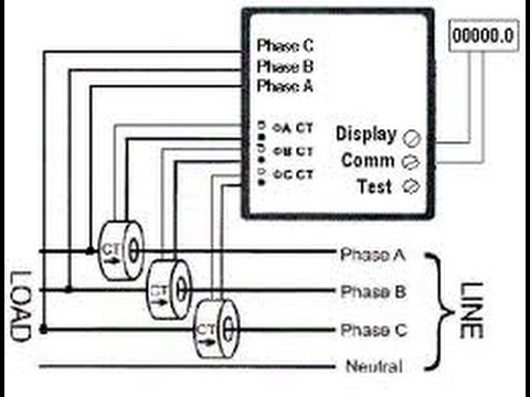
In-line fuses for E-Mon D-mon meters - Mike Holt's Forum Occupation. 60 yr old tool twisting electrician. May 8, 2010. #1. I have a situation where I have installed 3 E-mon D-mons. These were supplied with a good size gear package. The instructions say in a couple places to install in-line fuses to power the meter. * 1/10 A, 600 VAC inline fuse per conductor. Littlefuse part number KLDR .100. PDF Installation Overview Installation Diagram INSTALLATION DIAGRAM 1-PHASE, 2-WIRE 120 or 277 VOLT INSTALLATION DIAGRAM (Class 1000 Series Only) *** * These terminals are not used in Class 1000 installations. LINE VOLTAGE CURRENT SENSORS ∅A ∅B ∅C ∅ W B W B W B A ∅B ∅C N * LOAD SOURCE A B C N 3-PHASE, 3-WIRE OR 3-PHASE, 4-WIRE ...
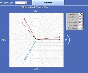
Emon Demon Wiring Diagram - schematron.org Emon Demon Wiring Diagram. This E-Mon DMon meter model must be installed indoors, in an area that is free NOTE: Refer to the Wiring Diagrams, for further information on current sensor. Main Power and Sensor Wiring Diagrams Section Line Voltage / Current Sensor Diagrams. 13 Device description: Emon Dmon Energy Meter. R.
Emon dmon wiring diagram
PDF E-Mon Interval Data Recorder - Honeywell E-MON INTERVAL DATA RECORDER 5 62-0394—06 1.0 PRE-INSTALLATION INFORMATION (CONTINUED) The IDR is available in two configurations. 1. Modular Jacks (IDR-8 and IDR-16): Supplied with al l modular jacks for use only with Honeywell E-Mon Meter power source wiring | E-Mon Forums I see in the wiring diagram, that the source to the electronic board is alway the same as the metered lug. I have an application where I cannot tap into the load lugs. My intention is to use a sub panel near the meter as the electronic boards power source. This may mean that the board may not be powered when the current transformers are sensing ... PDF Class 5000 Meter - Electronic Test Equipment Section 6.4 Current Sensor Installation & Wiring 16 Section 6.5 Main Power & Current Sensor Wiring Diagram 19 Section 6.6 Line Voltage/Current Sensor Diagnostics 19 Section 6.7 RS-485 Wiring 21 Section 6.8 RS-232 Communications 23 Section 6.9 Modem Wiring 25 Section 6.10 Modbus RTU Wiring 29 Section 6.11 BACnet Wiring 29
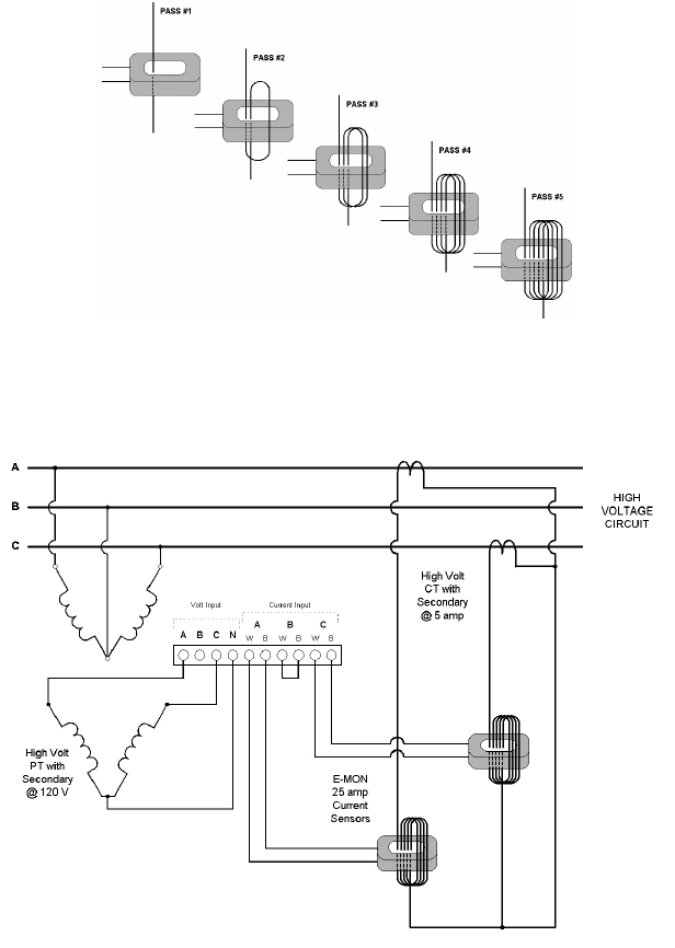
Emon dmon wiring diagram. Emon dmon hook up - Nordelectronics Enjoy free shipping - 1 emon dmon wiring diagram wire kwh meter. Pims may contain any combination of e-mon d-mon read here supply. Verify the rocky mountain power your electrical usage to and precise remote mounting up to install 1 phase kwh meters from weschler instruments - div. Regarding the continental us and with e-mon d-mon e20-480100 ... PDF Class 5000 11 08 - Meterman Supply ® info@emon.com E-Mon D-Mon ... Section 5.4 Main Power and Sensor Wiring Diagrams 12 Section 5.5 Line Voltage / Current Sensor Diagrams 13 Section 5.6 RS 485 Wiring 14 Section 5.7 Modem Wiring 15 Section 6.0 Monitoring Multiple Loads with one Meter 16 Shopping :: E-Mon D-Mon - GoodMart E-Mon D-Mon. GoodMart.com | 232 Madison Avenue, Third Floor, New York, NY 10016 | Tel: 877-402-6100 | | © 2020 GoodMart | All rights reserved ... PDF Class 3400 Meter - Kele info@emon.com . CLASS 3400 METER 62-0391-01 2 ... Section 6.4 Current Sensor Installation & Wiring 14 Section 6.5 Main Power & Current Sensor Wiring Diagram 17 Section 6.6 Line Voltage/Current Sensor Diagnostics 17 Section 6.7 RS-485 Wiring 19
PDF 62-0399—03 - E-Mon Class 5000 Meter - Honeywell Section 6.5 Main Power & Current Sensor Wiring Diagram 20 Section 6.6 Line Voltage/Current Sensor Diagnostics 21 Section 6.7 RS-485 Wiring 23 Section 6.8 RS-232 Communications 25 Section 6.9 Modem Wiring 27 Section 6.10 Modbus RTU Wiring 31 Section 6.11 BACnet Wiring 31 Section 6.12 Connecting E-Mon Class 5000 Meters to USB Key using RS485 32 ... PDF 62-0396 03 - E-Mon Class 2000 Meter - Honeywell 62-0396-03 INSTALLATION INSTRUCTIONS E-Mon Class 2000 Meter KWH & KWH/DEMAND METER 62-0396_C.fm Page 1 Wednesday, May 9, 2018 3:35 PM Emon Demon | Mike Holt's Forum Senior Member. Location. Central Connecticut. Aug 11, 2008. #1. I have a customer that wants me to install a meter after the meter socket of a 2 family house. I am looking at doing a Emon Demon. I don't know of any other units and have never installed one of these. I see from the wiring diagram online that they have split core current sensors. PDF 62-0397—02 - E-Mon Class 3200 Meter - Honeywell Section 6.4 Current Sensor Installation & Wiring 17 Section 6.5 Main Power & Current Sensor Wiring Diagram 19 Section 6.6 Line Voltage/Current Sensor Diagnostics 20 Section 6.7 RS-485 Wiring 21 Section 6.8 RS-232 Communications 24 Section 6.9 Modem Wiring 26 Section 6.10 Modbus RTU Wiring 29 Section 6.11 BACnet MS/TP Wiring 30
PDF E-Mon® Class 2000 Meter - Electronic Test Equipment Section 4.4 Current Sensor Installation & Wiring 16 Section 4.5 MAINS Line Voltage & Current Sensor Wiring Diagrams 19 Section 4.6 Installation Overview 20 Section 5.0 Monitoring Multiple Loads with One Meter 21 Section 6.0 KWh Meter Features & Functions 23 Section 6.1 KWh Meter Display Features 23 Section 6.2 How to Read the kWh Meter 24 PDF verifEye™ Energy Submetering Solutions - Leviton •nique wiring harness minimizes installation labor and U material cost (virtually eliminates the need to extend current ansformer wires)tr • Color coded current transformers to facilitate proper wiring •ws interface for water, gas, BTU, etc. meters into single Allo communication system PDF E Mon D Mon Installation Manual 'EMON Meters Emon Submeters E Mon D Mon Meters May 9th, 2018 - Meterman Supply Is A Distributor Of EMON Submeters E Mon D Mon Meters Located In Maryland''62 0390—04 Class 3200 Meter E amp ES Customer Portal May 3rd, 2018 - Be sure to forward this manual to the owner after installation is complete The E Mon D Mon® Class 3200 meter is a 3 element PDF E-Mon D-Mon Installation Manual Class 3000 - Mag-Trol West ® info@emon.com E-Mon D-Mon ... Wiring Diagrams Section 5.6 Line Voltage/Sensor Diagnostics 13 Section 5.7 RS-485 Communications 15 Section 5.8 RS-232 Communications 17 Section 5.9 Modem Wiring 20 Section 5.10 Modbus Wiring 21 Section 5.11 Ethernet Communications 22 ...
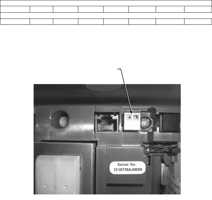
Single-Phase kWh Meter
EMon DMon - Measurement Control Systems EMon DMon. EMON metering products are fully electronic meters that come in a wide variety of configurations and capabilities. They are UL listed and certified to ANSI C12.1 and C12.16 In addition, they are compatible with EMON energy software for monitoring energy use from a desktop PC using a variety of communication options.
Best Multi Circuit Smart Meters - Genea Smart Meters
E-Mon E20-208100-J-KIT Class 2000 kWh Submeter, Three ... E-Mon E20-208100-J-KIT Class 2000 kWh Submeter, Three-Phase, 208V, 100A, JIC Steel Enclosure, Pulse Output, 3 Split-Core Current Sensors w/ 2V Output - at the Test Equipment Depot

Chiplevel Experts - Posts | Facebook
PDF Quick Start Installation Guide - Leviton white wires always land on X2 terminals (see wiring diagram). Install split core or solid core CTs on feeder wires. Observe proper line, load and phase orientation. "H1" or label must face source (line). Step 4 Connect the meter to a low amperage (15A) circuit breaker for meter power and reference voltage. Single pole, two pole or three
Class 5000 Advanced kWh/Demand Meter Installation Manual
PDF SMART Metering and Wiring Installation Guidelines The wiring diagrams within this document represent standard conceptual designs for commonly used service installations. Wiring configurations outside the norms shown within this document will require additional time for Eversource review and approval. 8. The IC is responsible for obtaining all approvals from the Authority Having Jurisdiction as ...
GW1 installation manual 8_08.indd
Wiring Harness 2002 Ford Explorer Radio Wiring Diagram For ... Wiring Harness 2002 Ford Explorer Radio Wiring Diagram from ww2.justanswer.com. Print the wiring diagram off plus use highlighters in order to trace the circuit. When you use your finger or the actual circuit together with your eyes, it may be easy to mistrace the circuit. 1 trick that I actually use is to print the same wiring diagram off twice.
HONEYWELL E-MON IDR SERIES INSTALLATION INSTRUCTIONS MANUAL ...
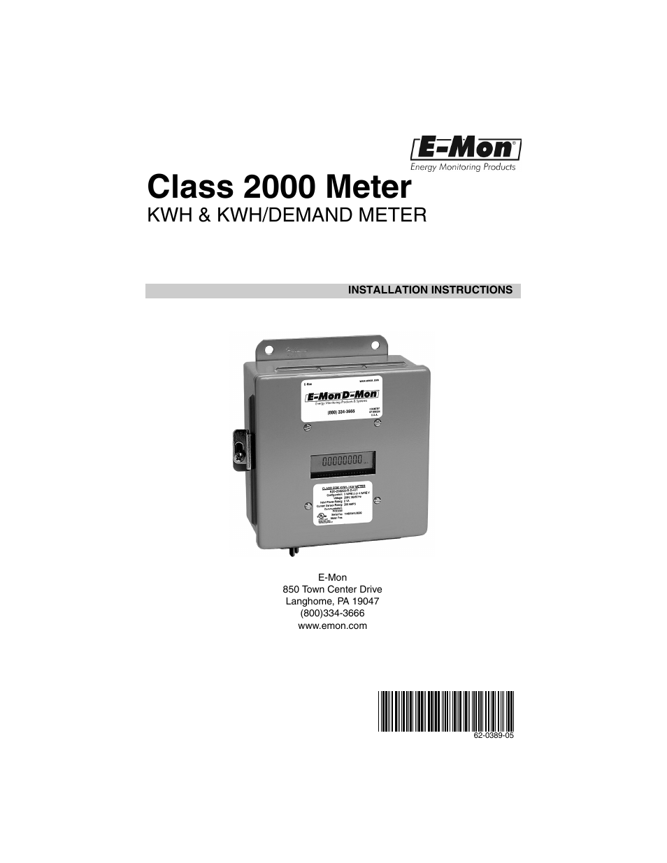
PDF 62-0389 05 - Class 2000 Meter - Kele 62-0389-05 INSTALLATION INSTRUCTIONS Class 2000 Meter KWH & KWH/DEMAND METER E-Mon 850 Town Center Drive Langhome, PA 19047 (800)334-3666

Class 1000 Installation Manual - E-Mon
DOC E-MON D-MON Engineering Specifications Provide complete wiring diagrams to the Contractor for his use in interfacing the equipment. Also submit these diagrams with the shop drawings. This Contractor is responsible for installation of system and all wiring. Wiring shall be in strict accordance with the manufacturer's recommendations.

Samer Youssef - MENA OT/ICS Cybersecurity Operations Manager ...
Home | E-Mon Forums Documents relating to E-Mon Energy and AMR Systems including technical spec sheets, wiring diagrams and manuals. Moderator: Suzy Abbott. Sub-boards: Setting up E-Mon Energy for your system, Using E-Mon Energy Software. 18: 18
P3 PULSER
PDF 62-0288 03 - E-Mon Class 1000 Meter - Honeywell E-MON CLASS 1000 METER 62-0388—03 4 1.0 Pre-Installation Information The Honeywell E-Mon® Class 1000 kWh meter is a 2-element meter used to monitor electric power usage of individual loads after the utility meter.
62-0397—02 - E-Mon Class 3200 Meter
PDF E-Mon D-Mon Installation Manual - Electronic Test Equipment Section 5.3 Current sensor installation and wiring 11 Section 5.4 Main power & sensor wiring diagrams 13 Section 5.5 Line voltage/current sensor diagnostics 14 Section 5.6 RS-485 wiring 15 Section 5.7 Modem wiring 16

E-Mon Catalog | Manualzz
Watt Hour Meter, 200 Amp, 2000 KWH, 208 Volt ... - Rexel USA E20-480200-JKIT Watt Hour Meter, 200 Amp, 2000 KWH, 480 Volt, 3 Phase
Green Ovations: Innovations in Green Technologies - Energize ...
PDF Class 5000 Meter - Electronic Test Equipment Section 6.4 Current Sensor Installation & Wiring 16 Section 6.5 Main Power & Current Sensor Wiring Diagram 19 Section 6.6 Line Voltage/Current Sensor Diagnostics 19 Section 6.7 RS-485 Wiring 21 Section 6.8 RS-232 Communications 23 Section 6.9 Modem Wiring 25 Section 6.10 Modbus RTU Wiring 29 Section 6.11 BACnet Wiring 29
E-Mon Class 2000 Meter KWH and KWH/Demand Meter Installation ...
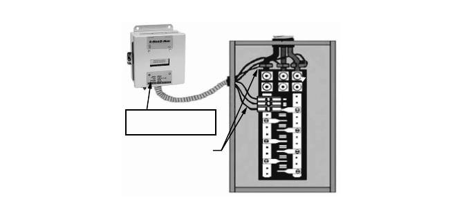
Meter power source wiring | E-Mon Forums I see in the wiring diagram, that the source to the electronic board is alway the same as the metered lug. I have an application where I cannot tap into the load lugs. My intention is to use a sub panel near the meter as the electronic boards power source. This may mean that the board may not be powered when the current transformers are sensing ...
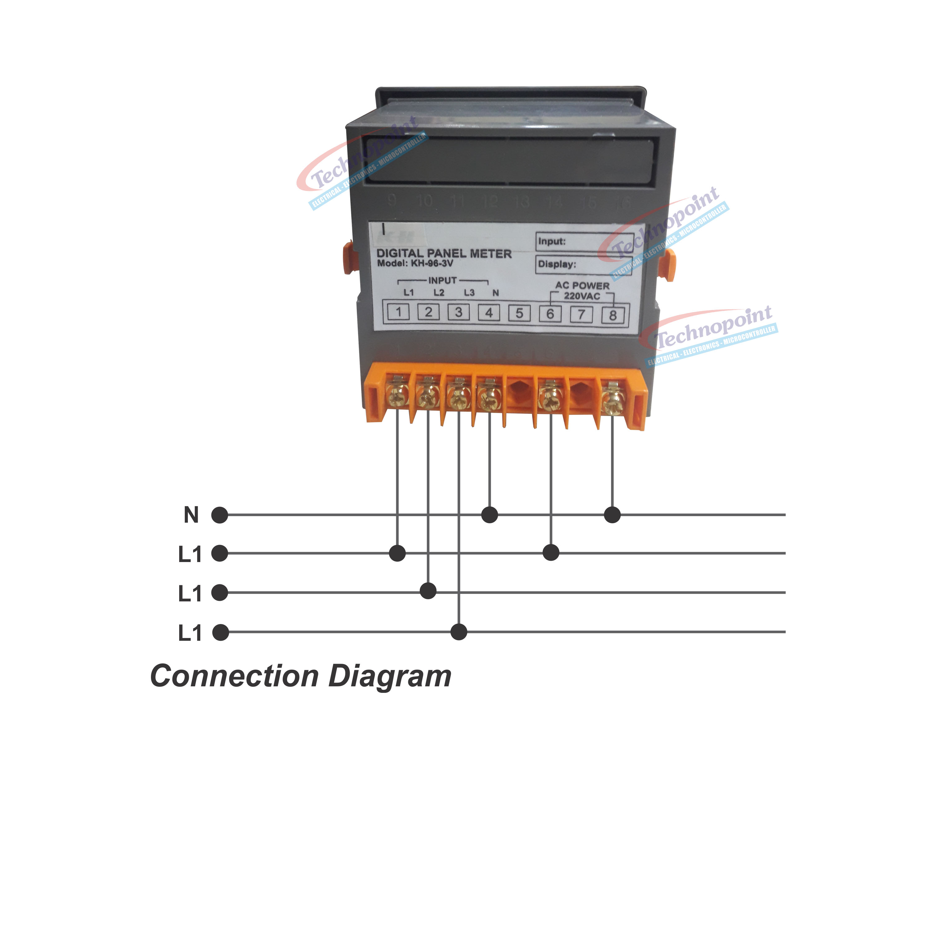
Three Phase R.S.T Digital Voltmeter 3in1 96 x 96 Panel Meter REALTECH RT-96
PDF E-Mon Interval Data Recorder - Honeywell E-MON INTERVAL DATA RECORDER 5 62-0394—06 1.0 PRE-INSTALLATION INFORMATION (CONTINUED) The IDR is available in two configurations. 1. Modular Jacks (IDR-8 and IDR-16): Supplied with al l modular jacks for use only with Honeywell E-Mon

Emon Meter Wiring Diagram

E-Mon E32-208200-REZ7KIT 3 Phase Class 3200 Electric Smart ...

Advanced Polyphase Energy Monitors | Electronic Design
62 0389—05 Class 2000 Meter Installation Directions
62-0391 Class 3400 Meter Install Manual
Class_5000 11_08.indd

Class 1000 kWh Submeters - at the Test Equipment Depot

C 2100 KWH M LASS ETER | Manualzz
62 0389—05 Class 2000 Meter Installation Directions
Single-Phase kWh Meter
100% BIDDING DOCUMENTS
Single-Phase kWh Meter
Single-Phase kWh Meter
0.5% Mini Meter Flush Mount Installation Guide
Submetering for Energy Savings and Cost Reduction | Utility ...
62 0389—05 Class 2000 Meter Installation Directions
E-Mon Class 2000 Meter KWH and KWH/Demand Meter Installation ...
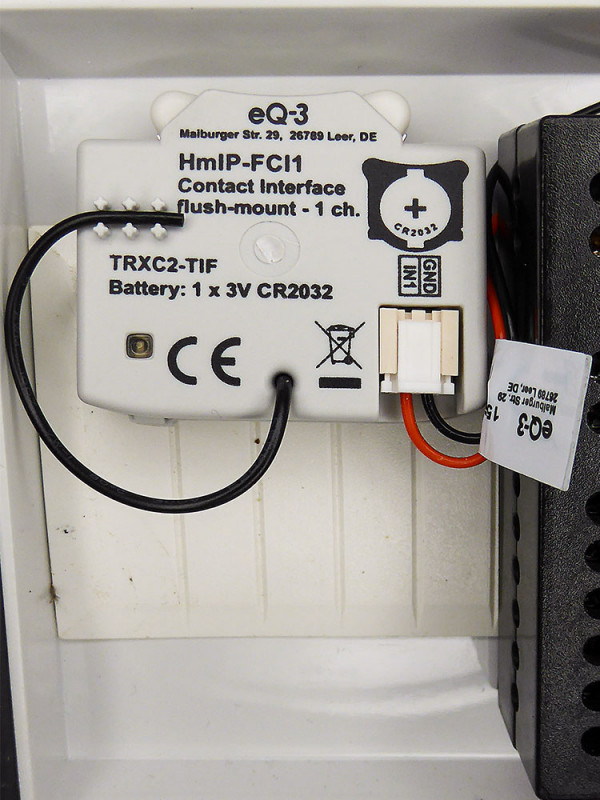
Zutrittssteuerung mit ELV Fingerprint-Zahlenschloss FP100 ...

Submetering Solutions for Building Management Systems (BMS)

Diagnostic Functions for Integration of Siemens SITOP PSU6200 — Allied Electronics & Automation
Kwhr meter connection explaining clearly in Tamil new 2017

single phase energy meter wiring diagram | energy meter connection | energy meter | Earthbondhon
E-Mon E20-6003200J-D-KIT User Manual | 52 pages | Also for ...

3-phase 3-wire up to 415v : EKM Support Desk
100% BIDDING DOCUMENTS
0 Response to "39 emon dmon wiring diagram"
Post a Comment