42 Transfer Function Block Diagram
What is the transfer function of this block diagram Transfer function block diagram. 1. Find the difference equation and draw the simulation diagram. 4. Find transfer function from root locus and step response diagram? 3. Poles and zeros of a transfer function. 0. Block diagram for a complex impulse response. 0. Inverse Fourier of Two-Pole Transfer Function. Transfer function example block diagram Block Diagrams of Control System The block diagram is to represent a The resultant signal is the input of a control system block of transfer function G Block Diagram Manipulation rearranging the diagram such that you end up with only one block. For example, Since each transfer function represents a linear.
academic.csuohio.edu › dong_l › EEC440Lecture 4: Transfer Function and Block Diagram (Continued) 2. Block diagram models The block diagram is a diagrammatic means to represent the cause-and-effect relationship of system variables. It consists of unidirectional, operational blocks that represent the transfer function of the variables of interests. Fig.4: Components of a block diagram for a linear, time-invariant system

Transfer function block diagram
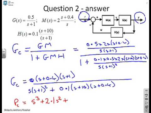
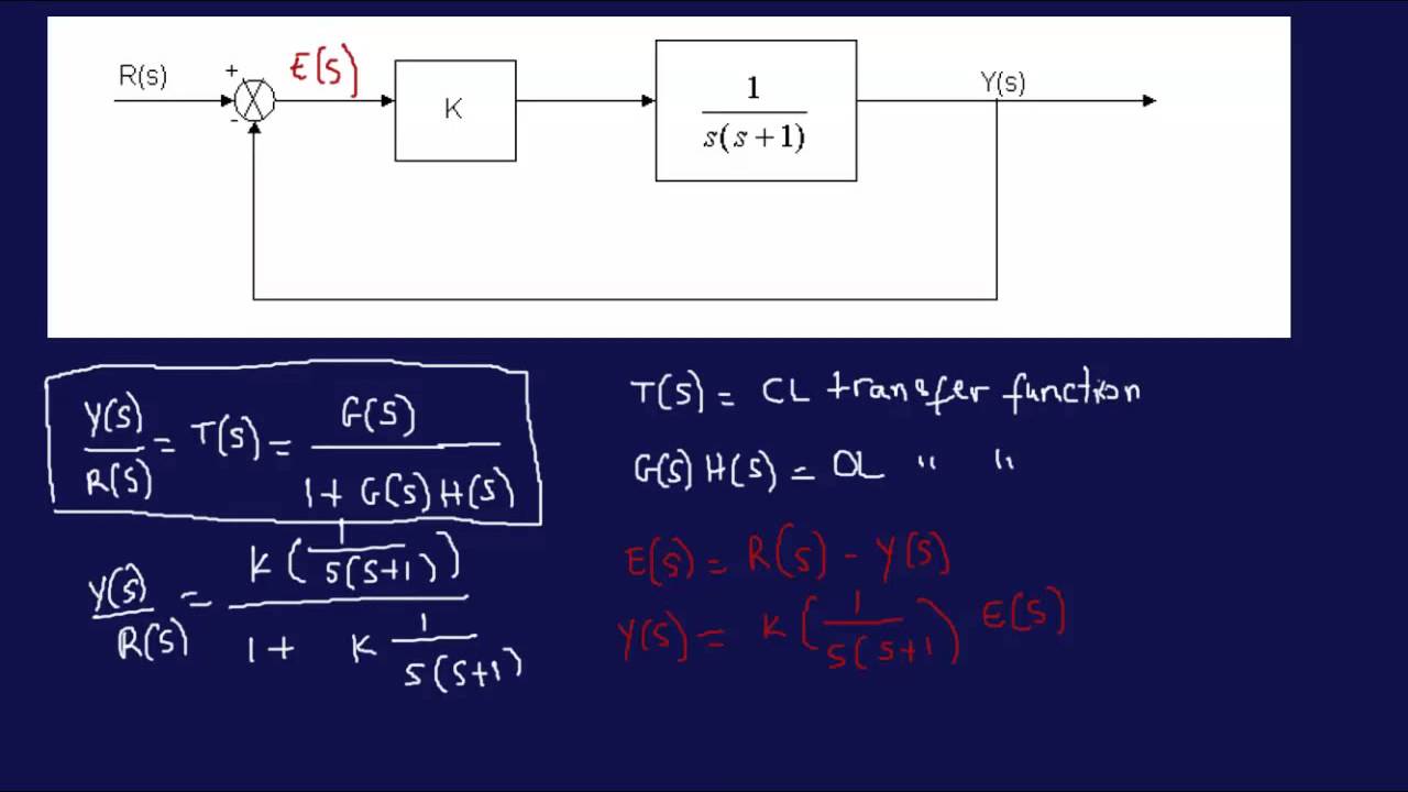
Block Diagram of Transfer Function - Transfer Function ... Subject - Control SystemVideo Name - Block Diagram of Transfer FunctionChapter - Transfer Function, Block Diagram and Signal Flow GraphFaculty - Prof. Shruti... PDF Worked examples block diagrams transfer functions Worked Examples on block diagrams/transfer functions 31st January 2012 1. For the closed-loop feedback control system with input R and output X shown in the figure above, derive the open-loop transfer function and the closed-loop transfer function. Answer: For the inner negative unity-feedback closed loop system, using GH G Gc s 1 ( ) we have ... Block diagram reduction Techniques - Transfer Function A block diagram can be used simply to represent the composition and interconnection of a system. Also, it can be used, together with transfer functions, to represent the cause-and-effect relationships throughout the system. Transfer Function is defined as the relationship between an input signal and an output signal to a device. Block diagram rules
Transfer function block diagram. Block Diagram Transfer Function - MATLAB & Simulink Block Diagram Transfer Function. Follow 19 views (last 30 days) Show older comments. Campbell Biology on 31 May 2019. Vote. 0. ⋮ . Vote. 0. Answered: Raj on 31 May 2019 How do I obtain the trnsfer diagram for the following block diagram with matlab command? Thanks you very much 0 Comments. PDF Chap. 71 Block Diagram Algebra and Transfer Functions of ... 160 BLOCK DIAGRAM ALGEBRA AND TRANSFER FUNCTIONS OF SYSTEMS [CHAP. 7 Let the - 1 block be absorbed into the summing point: Step 4c Step 5: By Equation (7.3), the output C, due to input U is C, = [G2/(1 + G1G2)]U. The total output is C=C,+C,= [ ~ 1 +G2G2] [ A] [ A] IGIR + 7.8 REDUCTION OF COMPLICATED BLOCK DIAGRAMS The block diagram of a practical feedback control system is often quite complicated. Transfer function verification and block diagram ... Transfer function verification and block diagram simplification of a very high-order distributed pole closed-loop servo by means of non-linear time-response simulation Linear frequency domain methods are inadequate in analyzing the 1975 Viking Orbiter (VO75) digital tape recorder servo due to dominant nonlinear effects such as servo signal limiting, unidirectional servo control, and static ... Transfer function to block diagram in state space analysis ... How to draw block diagram from given transfer function in state space analysis,Transfer function to block diagram conversion,Full Series-Semiconductor Device...
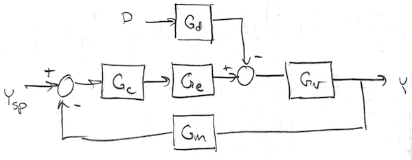
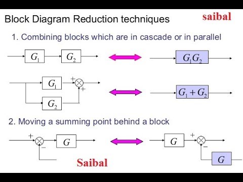
Control Systems - Block Diagram Reduction Step 1 − Find the transfer function of block diagram by considering one input at a time and make the remaining inputs as zero. Step 2 − Repeat step 1 for remaining inputs. Step 3 − Get the overall transfer function by adding all those transfer functions. The block diagram reduction process takes more time for complicated systems. Simulink Transfer function/ block diagram - MathWorks This block diagram can certainly be recreated in Simulink. I suggest you start with 'Transfer Function' blocks and 'Sum' blocks, to match the transfer functions and sums in the diagram. I am not sure what the 'F' blocks in your diagram refer to, but if they are simply gains, then you can use a 'Gain' block to represent each one. TRANSFER FUNCTIONS AND BLOCK DIAGRAMS - Academia.edu Write down the transfer function Y (s)/R (s) of the following block diagram. R (s) Y (s) K G (s) + _ a) For G (s) = 1/ (s + 10) and K = 10, determine the closed loop transfer function with MATLAB. b) For K = 1, 5, 10, and 100, plot y (t) on the same window for a unit-step input r (t) with MATLAB, respectively. Comment on the results. Control Systems - Block Diagrams - Tutorialspoint The above block diagram consists of two blocks having transfer functions G (s) and H (s). It is also having one summing point and one take-off point. Arrows indicate the direction of the flow of signals. Let us now discuss these elements one by one. Block The transfer function of a component is represented by a block.
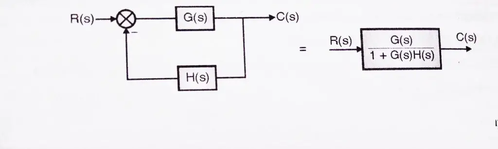
Transfer function of Block Diagrams | Exercise 1 Starting to study the way to find the transfer function of a block diagram in control systems you can find that you have to reduce by blocks until you have only one block to find the transfer function, this is a bit complicated when you have a block diagram with many components. Block Diagram of Control Systems (Transfer Functions ... Block Diagram of Closed Loop Control System. In a closed-loop control system, a fraction of output is fed-back and added to the system's input. If H (s) is the transfer function of the feedback path, then the transfer function of the feedback signal will be B (s) = C (s)H (s). At the summing point, the input signal R (s) will be added to B (s ... › control_systems › controlControl Systems - Block Diagram Algebra - Tutorialspoint The equivalent block diagram is shown below. Similarly, you can represent the positive feedback connection of two blocks with a single block. The transfer function of this single block is the closed loop transfer function of the positive feedback, i.e., $\frac{G(s)}{1-G(s)H(s)}$ Block Diagram Algebra for Summing Points › control-system-transfer-functionControl System Transfer Function - javatpoint Find the transfer function of the given network. Solution: Step 1. Step 2: By taking the Laplace transform of eq (1) and eq (2) and assuming all initial condition to be zero. Step 3: Calculation of transfer function. Eq (5) is the transfer function. Example- 2. Find the transfer function of the following diagram. Solution - Step 1:Apply KCL at ...
System block diagram for the linear local feedback model of ...
discrete signals - Transfer function block diagram ... Block diagram transfer function of a line. 1. DTFT and Inverse DTFT Homework Problem. 1. Drawing the modulus from a Transfer function. 1. How can I correctly plot an impulse_response() of a discrete transfer function? 1. Real Data Complex Transfer Function using H0, H1, H2 Estimators. 0.
Notebook
literature.rockwellautomation.com › idc › groupsLogix 5000 Controllers Function Block Diagram When an IREF specifies input data for a function block instruction, the data in that IREF is latched for the scan of the function block routine. The IREF latches data from program-scoped and controller-scoped tags. The controller updates all IREF data at the beginning of each scan as shown in this diagram.

Control theory - what is block diagram for these transfer ...
PDF Transfer Functions Transfer Functions In this chapter we introduce the concept of a transfer function between an input and an output, and the related concept of block diagrams for feedback systems. 6.1 Frequency Domain Description of Systems The idea of studying systems in the frequency domain is to characterize a

Transfer function block diagram of the electric steering gear ...
1817_09.pdf - 9 Transfer Functions and Block Diagrams ... 9 Transfer Functions and Block Diagrams Background Feedback control systems are made up of components that are reactive by nature. This means that each one has an input (sometimes more than one) and the means to generate an output. The inputs and outputs have a vari-ety of forms, but in process control the most common are process variables and instrument signals.

Block diagram of a transfer functions model of the control ...
PDF Block Diagrams Introduction 2. Simple Examples .. . mx bx s W As a block diagram we can represent the system by F (s) W(s) X (s) Fig. 1. Block diagram for a system with transfer function W(s). Sometimes we write the formula for the transfer function in the box representing the system. For the above example this would look like F (s) 1 ms2 + bs+ k X (s) Fig. 2. Block diagram giving the formula for the ...

Simplify the block diagram shown in the figure. Obtain the ...
en.wikipedia.org › wiki › Transfer_functionTransfer function - Wikipedia For example, the transfer function of a two-port electronic circuit like an amplifier might be a two-dimensional graph of the scalar voltage at the output as a function of the scalar voltage applied to the input; the transfer function of an electromechanical actuator might be the mechanical displacement of the movable arm as a function of ...

Closed-loop transfer function - Wikipedia
PDF C.02 Transfer Functions and Block Diagrams Chapter 2 Transfer Functions and Block Diagrams 4 2. Transfer Functions and Block Diagrams 2.1 Introduction - Review of Laplace transform - Using Laplace transform to solve a differential equation 2.2 Review of Laplace Transforms Definition: The Laplace transform off (t) , a sectionally continuous function of time, denoted by L[ f (t)], is ...
Wescott Design Services: Using Block Diagrams
11.5: Block Diagrams and Transfer Functions of Feedback ... Block Diagrams: Fundamental Form. The topology of a feedback system can be represented graphically by considering each dynamical system element to reside within a box, having an input line and an output line. For example, a simple mass driven by a controlled force has transfer function , which relates the input, force , into the output, position .
Closed-Loop Transfer Function Block Diagram - CircuitLab
PDF ET 438a Transfer Functions and Block Diagrams Find the ... Transfer Functions and Block Diagrams Find the transfer function and draw a block diagram for each of the circuits shown below. Fall 1998 hw38-7.doc. Title: Microsoft Word - HW38-7.doc Author: Carl Spezia Created Date:
Block diagram reduction technique(to find transfer function)(Rules & example with solution)
Transfer Functions in Block Diagrams - APMonitor Transfer Functions in Block Diagrams One source of transfer functions is from Balance Equations that relate inputs and outputs. Transfer functions are compact representations of dynamic systems and the differential equations become algebraic expressions that can be manipulated or combined with other expressions.

Answered: Find the transfer function of the… | bartleby
Transfer function block diagram - - StuDocu Transfer function: It is defined as the ratio of the Laplace transform of the output variable to the Laplace transform of the input variable, with all zero initial conditions. Block diagram: It is used to represent all types of systems.

Converting a transfer function to state space | Transfer ...
PDF SECTION 5: BLOCK DIAGRAMS - College of Engineering K. Webb ESE 499 3 Block Diagrams In the introductory section we saw examples of block diagrams to represent systems, e.g.: Block diagrams consist of Blocks - these represent subsystems - typically modeled by, and labeled with, a transfer function Signals - inputs and outputs of blocks - signal direction indicated by arrows - could be voltage, velocity, force, etc.
Section 1: Introduction
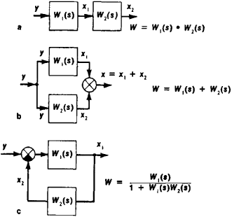
PDF 4.4 Block Diagrams - Rutgers University 4.4 Block Diagrams Using the Laplace transform linearity and convolution properties we can easily extend the concept of the transfer function to configurations of several connected linear systems. In that way we will find the equivalent transfer functions for cascade and parallel connections of systems, introduce the feedback (closed-loop)
Wescott Design Services: Using Block Diagrams
Determine transfer function from block diagram Determine transfer function from block diagram. I am having trouble to define in matlab the transfer function of the following block diagram. G11 is in series with Gc. Based on superposition principal I can assume that the disturbance signal z0*G12 is zero. Thus I may find the transfer function of the closed loop path.

Block Diagram Reduction to find closed loop transfer function for control system model in hindi
PDF Chap. 7] Block Diagram Algebra and Transfer Functions of ... The block diagram for n transfer functions G1,.Ga ..... G, in cascade is given in Fig. 7-11. Xl Xÿ Xn Fig. 7-11 The output transform for any block is equal to the input transform multiplied by the transfer function (see Section 6.1). Therefore X2 = XaG1, X3 = X2G2 .....

Mathematical models - Block Diagrams
› loop-transfer-functionLoop Transfer Function - an overview | ScienceDirect Topics The block diagram includes a comparator, a digital controller with transfer function C(z), and the ADC-analog subsystem-DAC transfer function G ZAS (z). The controller and comparator are actually computer programs and replace the computer block in Fig. 3.1 .
 eNotes: Mechatronics and Controls" width="832" height="235" style="width:100%;" onerror="this.parentNode.parentNode.remove();">
H1 align="center">eNotes: Mechatronics and Controls
Block diagram reduction Techniques - Transfer Function A block diagram can be used simply to represent the composition and interconnection of a system. Also, it can be used, together with transfer functions, to represent the cause-and-effect relationships throughout the system. Transfer Function is defined as the relationship between an input signal and an output signal to a device. Block diagram rules
Block diagrams 8 -- tutorial sheet on closed-loop transfer functions and use of MATLAB
PDF Worked examples block diagrams transfer functions Worked Examples on block diagrams/transfer functions 31st January 2012 1. For the closed-loop feedback control system with input R and output X shown in the figure above, derive the open-loop transfer function and the closed-loop transfer function. Answer: For the inner negative unity-feedback closed loop system, using GH G Gc s 1 ( ) we have ...

Block diagram 6
Block Diagram of Transfer Function - Transfer Function ... Subject - Control SystemVideo Name - Block Diagram of Transfer FunctionChapter - Transfer Function, Block Diagram and Signal Flow GraphFaculty - Prof. Shruti...
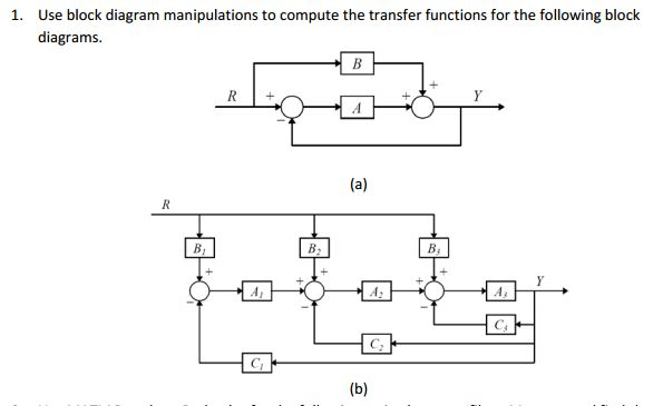
Solved Use block diagram manipulations to compute the | Chegg.com

A: block diagram of the open-loop postural system. B: block ...
Calculating a transfer function from a block diagram ...

Small perturbation transfer function block diagram of the ...

Transfer function block diagram representation of an isolated ...
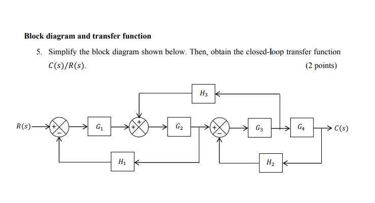
Solved Block diagram and transfer function 5. Simplify the ...
Engineer On A Disk
1 3.19 Find the transfer functions for the block diagrams in ...
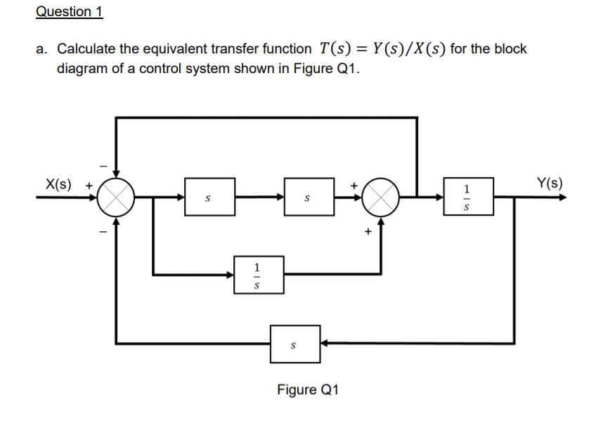
Solved a. Calculate the equivalent transfer function 𝑇(𝑠 ...

Solve for each block diagram. Do quick please! 3.19 Find the ...
Deriving Transfer Function from Block Diagram 1-FE/EIT Exam Review
control system - Getting transfer function from block diagram ...
Control Systems - Block Diagram Reduction
ECE 486 Control Systems
Solved The transfer function block diagram of a system ...
Transfer Functions in Block Diagrams | Dynamics and Control
Block Diagram, Automatic-Control | Article about Block ...

PROBLEMS B-2-1. Simplify the block diagram shown in Figure 2 ...

Reduce the block diagram shown in Figure 5.9 to a single ...
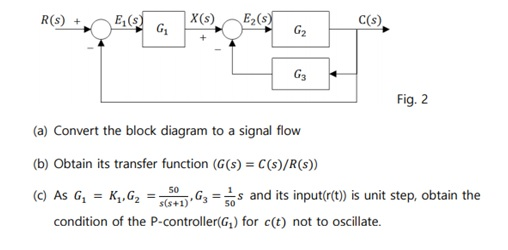
Solved C(s) G2 G3 Fig. 2 (a) Convert the block diagram to a ...

Transfer function block diagram of DC motor. | Download ...
Block Diagram Reduction Shortcut Rules In Control System !!
Transfer Function Block Diagram Confirmation - Signal ...
0 Response to "42 Transfer Function Block Diagram"
Post a Comment