42 Horn Button Wiring Diagram
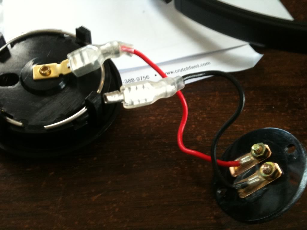
Horn Button Wiring Diagram Horn Button Wiring Diagram. June 10, 2019. Horn Wiring. a-dingli.tripod.com. Dyna Ignition Wiring Diagram. Nc Contact Switch. Dimmer Switch Wiring. Horn button wiring - JeepForum.com I'm replacing my Grant Steering wheel with an original Jeep steering wheel. I've removed the Grant wheel, and now I'm trying to figure out where the black horn wire should be connected. If I hold the black wire into the round cup-like thing...
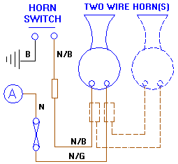
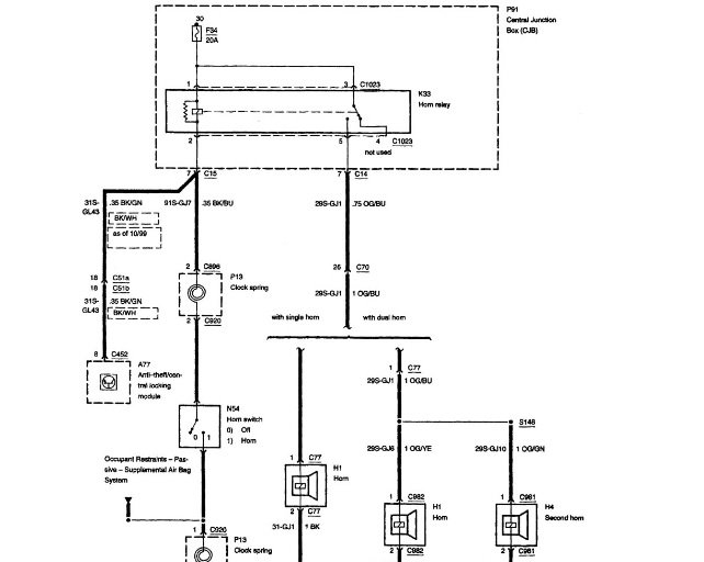
Horn button wiring | Adventure Rider The wiring diagram is useless and utterly lame. It shows the wires going to a box marked "horn" No diagram of a switch, or where the leads go. The diagram clearly shows the blue/yellow positive lead from the fuse block to the horn, and the ground wire switched through the handlebar button.
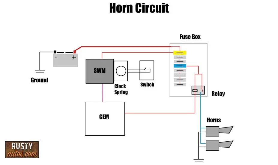
Horn button wiring diagram
PUSH BUTTON HORN WIRING DIAGRAM - Auto Electrical Wiring... Author: Gary Horns & Wiring Diagram - YouTube Click to view on Bing3:33Jan 18, 2011Horns & Wiring DiagramAmazon Printed Bookshttps the horn button if it has two post connectors. This will be a ground wire. Run the ground wire inside the dash board. Crimp a screw eyelet on the end of the... Electrical Catalog - Willys Ford Kaiser M38 M38A1 Jeep 1/4 ... Horn Switch Kit - M38 & M38A1. ... Horn Rod, Horn Rod Washer, Horn Button Cap and Steering Wheel Nut. This kit contains parts made in the USA. The "Short" Kit contains our new high quality reproduction Horn Switch, ... Comes with a wiring diagram (use the manual as well). PDF 08_3211348_en_OM.pdf | WIRING DIAGRAM WIRING DIAGRAM. Components A6 CDI controller B1 Throttle position sensor B3 Wheel speed sensor E6 Thermoswitch (EXC-F SIX DAYS) G1 Battery G2 switch S2 Front brake light switch S5 Tripmaster switch (optional) S6 Light switch S7 Horn button, short circuit button S8 Flasher switch S10 Electric...
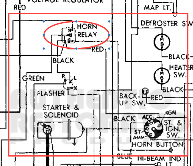
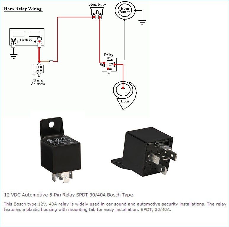
Horn button wiring diagram. horn wiring diagram Questions & Answers (with Pictures) - Fixya Find solutions to your horn wiring diagram question. Get free help, tips & support from top experts on horn wiring diagram related issues. ...horn wiring diagram. The relay has two sides, the switch side,right side in diagram, and the control side, left side in diagram. Peugeot all models wiring diagrams - general 25 - horns. 26 - headlamps, tail lamps, number plate lamps, side lamps and indicator lamps. 11 - reading wiring diagrams: N: harness identification. O: fuse box diagram. 1045: auxiliary re-arming push button. 1086: alarm starter cut-off relay. 1100: distributor. Camry Electrical Wiring Diagram - Toyota Camry Repair 05-02-2022 · Internal wiring for each junction block is also provided for better understanding of connection within a junction block. Wiring related to each system is indicated in each system circuit by arrows (from_, to_). When overall connections are required, see the Overall Electrical Wiring Diagram at the end of this manual. WIRING DIAGRAMS :: 1984 - 1991 :: Jeep Cherokee (XJ) :: Jeep... WIRING DIAGRAMS. 1988 Jeep Cherokee. Horn Relay 1 (C 2). Wiper/Washer System 3 (D-E 8-11). WIRING DIAGRAMS.
Push Button Horn Wiring Diagram For Your Needs Read wiring diagrams from unfavorable to positive and redraw the signal being a straight range. All circuits are usually the same - voltage, ground, single component, and changes. Push Button Horn Wiring Diagram Source: a-dingli.tripod.com. KTM - Motorcycles Manual Pdf, Wiring Diagram & Fault Codes 17-02-2022 · I am owning a TVS XL 100 . I am interested to know my two wheelers wiring system. The basics of where the electricity is developed and how the system is operated. I need the wiring diagram pls.In the present site you have a search button for wiring diagram electrical but i dont find any diagram . kindly post the electrical wiring diagram pls. #242 VW Tech Article 1968-69 Wiring Diagram - JBugs VW Tech Article 1968-69 Wiring Diagram. ... Brake warning light with test button O1 ... Cable Connector for Horn under front luggage compartment lining T3 PDF TR250 - 6 wiring diagrams in color.cdr Triumph TR250 - TR6 wiring diagrams. HORN BUTTON.
Push Button Horn Wiring Diagram - ZTXXXX Diagram Push Button Station Wiring Diagram Full Version Hd. Index Of Wp Content Uploads 2018 02. Horn Problem Morris Minor Owners Club. Diagram Suzuki Gixxer Wiring Diagram Book Full Version Hd. What Is The Colour Code For The Hooter Wires Fixya. Icfm01itw Fhss Intelligent... Horns & Wiring Diagram - YouTube Horns & Wiring Diagram. Смотреть позже. Horn button Wiring Diagram 8466 Switch Wiring... | autocardesign Related Posts of "Horn button Wiring Diagram 8466 Switch Wiring Diagram Audi Wiring Diagram Schematic". Digital Car Horn : 12 Steps (with Pictures) - Instructables 11 wires for the buttons and the 12th wire for ground. Instead of running individual ground wires from each button to the Audio FX board, daisy chain a To test the horn, either start the car or turn the key to the "accessory position". You may hear a slight pop from the horn, indicating that the control pad...
Wiring diagram - Custom Billet Buttons Basic wiring skill is required to install these button; if you install a "Two Step" etched billet button on your horn, chance are good your Single color LED are not polarity sensitive. Because the LED have their own pin on the button you can have full control over them. It is easy to wire them so they light on
HeadLight & Horn A wiring diagram of the complete system is shown below. On the DPDT toggle switch, the center poles (my switch had 2 poles) are to be In Photo 8, the female terminal connector was for the wires leading to the bike. Pin 1 was for the green wire on the horn button (actually my horn button wire was black).
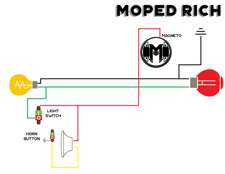
Puch Moped Horn Wiring Diagram (Chrome Oval Switches) | PDF How does the horn button play into the circuit? Since the Blue w/Black wire going to the horn is already energized, the The horn button in it's relaxed state (not being pushed) is actually making contact to a chassis ground. This in turn grounds out the energy flowing through the Blue w/Black wire.
horn button wiring diagram - Create Web Buttons No Coding... Air horn wiring diagram air horn wiring diagram air horn wiring diagram compressor air horn wiring diagram switch every electric structure is composed of various unique pieces. The single wire button will require only one wire connection which will be a hot positive wire to the fuse block or to...
Tracker Boats Wiring Diagram | TackleReviewer Mar 27, 2016 · I have 92 tracker pro 17 evinrude 50 just got it I need the wiring diagram for the lights, pumps and evering, plus how many pumps and plumbing as well PLEASE bear with me, im a 20 yr vet from 72-92 leagally blind and have tunnel vision meaning looking thru a straw at 10 feet can you help thanks ray
Horn button wiring | Team Chevelle Horn button wiring. Jump to Latest Follow. If so i'm guessing the button is already grounded thru the mounting screws and I would just need to run 1 control wire from the relay up thru the column and to the connector on the button, and the other to ground, and should work?
WIRING DIAGRAM INDEX, 12V - Mack Trucks horn 15a a b batt ign ems illum ems batt ign illum power distribution 2/2 wiring diagram: ab cb61 body batt. stud 20a a b cb67 cir. brkr., open a b cb68 cir. brkr., cigar lighter 15a a b f71 fuse, trans (batt) 10a a b f25 fuse, hvac cab 30a a b x2d1−0.8 frc1:b2 f63 fuse, instr cluster (ems) 5a a b f64 fuse, dpf, ign b10a f69 fuse, eat ems 5a ...
2021 Toyota Tundra, Alarm/Remote Start Wiring 07-02-2022 · 2021 Toyota Tundra, Alarm/Remote Start Wiring - Hello - Might anyone have a remote start / alarm diagram for a 2021 Toyota Tundra with push button start? Any help would be greatly appreciated. Thanks in advance....
Motorcycle Horn Relay Diagram and Gm Horn Relay Wiring - Wiring... how to wire a 5 pin relay diagram 20 wiring images five prong electrical schematic efcaviation com 12v dorman 4 autobonches bosch pole ipf driving light with for 12 volt circuit and in post u2022 awesome photos image why headlights youtube warn series 18 winch solenoid get free lights pdf description...
Wiring Diagrams « Myrons Mopeds Garelli Wiring Diagrams: All have CEV 3-wire magnetos with external ignition ground powering the brake light. Garelli wiring is functionally the same as "Minarelli" Wiring on many Italian mopeds. Unplugging one of the horn wires, then pressing the horn button stops the engine. In addition to that...
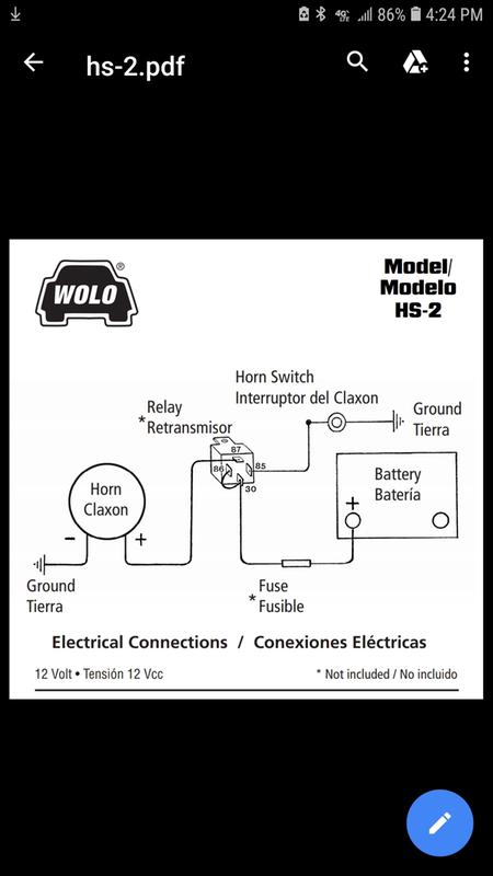
Steering Column Wiring Diagrams - Flaming River to the vehicle’s wiring or other components may occur. Grounding the BLACK WIRE will trigger the horn relay in the vehicle to sound the horn. Contact with ground can be interrupted by the horn button. See below for an appropriate horn relay wiring diagram. 87a +12V +12V 30 86 85 87 Horn Button Ground Horn Relay Main Power Horn Relay Power
(PDF) Schneider Electric Wiring Diagram Book | Engineer ... This book contains examples of control circuits, motor starting switches, and wiring diagrams for ac manual starters, drum switches, starters, contactors, relays, limit switches, and lighting contactors.
PDF Electrical wiring diagram WIRING DIAGRAM. Provides circuit diagrams showing the circuit connections. DIODE A semiconductor which allows current flow in only one direction. HORN An electric device which ∗ Engine Immobiliser ∗ Push Button Start System ∗ Steering Lock ∗ Wireless Door Lock Control...
Atlas Turnout Wiring Diagram - schematron.org Oct 31, 2018 · Control Panel Wiring (with LED's) - How To Idea on motorizing Atlas turnouts for under $10 - Duration: Wiring a gauge separating turnout: I don't know what this thing is really called. It is a track work arrangement that separates a dual gauge track into a standard gauge track and a narrow gauge track.
VW Parts | JBugs.com: 1971-1979 VW Horn Wiring Diagram 1954-1959 VW Horn Wiring Diagram. 1954 through 1959 Beetles the ground circuit starts at the steering box to coupler joint which is grounded past the rubber steering coupler with a ground strap, grounding out the metal steering shaft. When the horn button is pressed the ground signal is...
3 Way Handlebar Switch w/ Horn Button - Wiring Diagram - 46-68900 3 Way Handlebar Switch w/ Horn Button - Wiring Diagram - 46-68900.
Wiring Diagram - Auto - SmartDraw wiring diagram auto electrical wiring diagram drawn by checked date scale sheet no. ammeter distributor starter fuel gage breaker ignition coil light switch dome light tail stop plate instrument lights foot selector switch current & voltage regulator generator field gen bat gas tank unit horn button parking lamp sealed beam horn junction block beam
Wiring Diagram Book - Daltco Horn, Alarm, Siren,etc. Meter (indicate type by letters). A selector push button may be used to obtain jogging, as shown above. In the Run position, the selector-push button provides normal 3-wire control. Wiring Diagram. Class 8502 Type PE Contactor w/ Class 9065 Type TE Overload Relay.
PDF ENG51987_S1.cdr | Component wiring diagrams Wiring diagram. Horn 0. splice262_444. Other part of this component see sheets GA1-GB1-GB2-GQ Switch, push button, horn. 10p black. S02.
PEUGEOT - Car PDF Manual, Wiring Diagram & Fault Codes DTC 12-01-2015 · horn wiring diagram for Toyota auris 2008 model #359. Liz (Wednesday, 20 October 2021 02:55) I need a great wall steed Ute 2018 ... Toyota sienna LE wire diagram for stereo none JBL Need to know how to find the wires going to the steering wheel stereo button from the stock stereo. I am putting a after market stereo in that has the ...
Horn button wiring diagram Purchase your universal horn button kit. The single wire button requires that you mount the . Or does it not matter which side you hook up to? Can you pride wiring diagram please? Horn button install on my Ford f100.
PDF 35 Wiring diagram. 129 --- Ground connection, in dual-tone horn wiring harness. E22 --- Windshield Wiper/Washer Switch H --- Horn Button J31 --- Wiper/Washer Intermittent Relay T4b --- 4-Pin Connector T5c --- 5-Pin Connector.
Wiring Diagram For Horn Button - Free Catalogs A to Z 4 hours ago Car Horn Wiring Diagram - Lorestan - Car Horn Wiring Diagram. Wiring Diagram includes many comprehensive illustrations that display Horn button wire - Studebaker Drivers Club Forum. Just Now According to the wiring diagram, the horn button picks of (-) polarity and transmits...
PDF 08_3211348_en_OM.pdf | WIRING DIAGRAM WIRING DIAGRAM. Components A6 CDI controller B1 Throttle position sensor B3 Wheel speed sensor E6 Thermoswitch (EXC-F SIX DAYS) G1 Battery G2 switch S2 Front brake light switch S5 Tripmaster switch (optional) S6 Light switch S7 Horn button, short circuit button S8 Flasher switch S10 Electric...
Electrical Catalog - Willys Ford Kaiser M38 M38A1 Jeep 1/4 ... Horn Switch Kit - M38 & M38A1. ... Horn Rod, Horn Rod Washer, Horn Button Cap and Steering Wheel Nut. This kit contains parts made in the USA. The "Short" Kit contains our new high quality reproduction Horn Switch, ... Comes with a wiring diagram (use the manual as well).
PUSH BUTTON HORN WIRING DIAGRAM - Auto Electrical Wiring... Author: Gary Horns & Wiring Diagram - YouTube Click to view on Bing3:33Jan 18, 2011Horns & Wiring DiagramAmazon Printed Bookshttps the horn button if it has two post connectors. This will be a ground wire. Run the ground wire inside the dash board. Crimp a screw eyelet on the end of the...


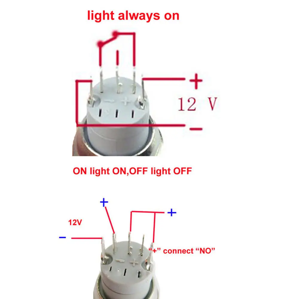


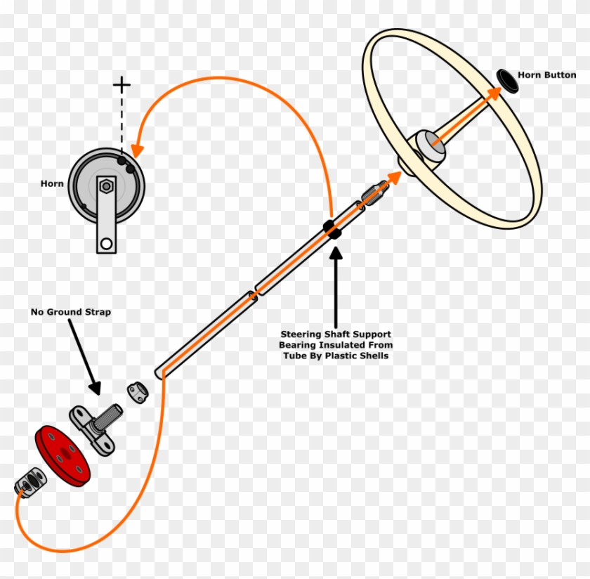


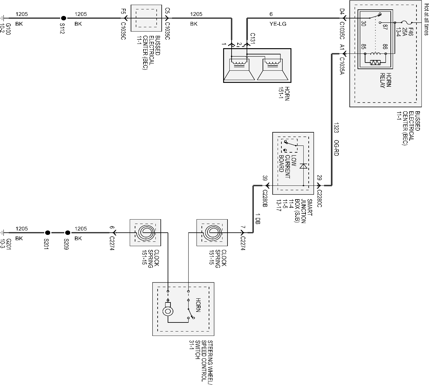







0 Response to "42 Horn Button Wiring Diagram"
Post a Comment