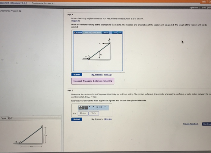
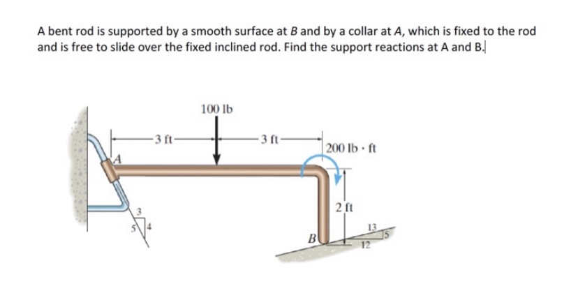
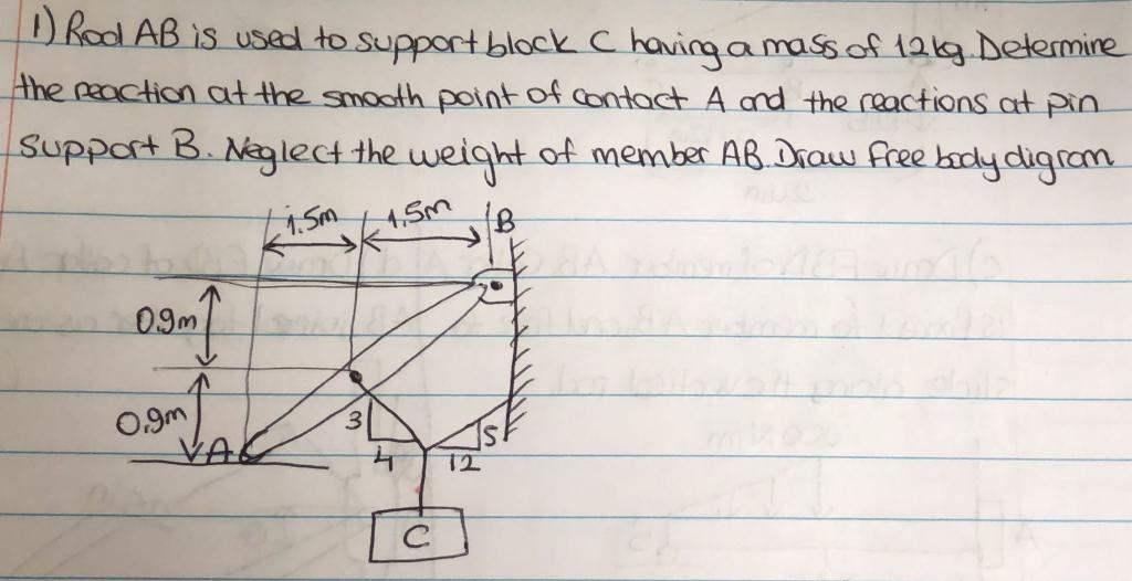
41 Draw A Free-body Diagram Of The Rod Ab. Assume The Contact Surface At B Is Smooth.
Problem 326 | Equilibrium of Force System - MATHalino Reactions at Smooth Contact Surfaces of Stacked Cylinders - Equilibrium of Force System. Problem 326 The cylinders in Fig. P-326 have the indicated weights and dimensions. Assuming smooth contact surfaces, determine the reactions at A, B, C, and D on the cylinders. ... free body diagram. FBD Drawing Free-Body Diagrams - Physics Classroom Drawing Free-Body Diagrams. Free-body diagrams are diagrams used to show the relative magnitude and direction of all forces acting upon an object in a given situation. A free-body diagram is a special example of the vector diagrams that were discussed in an earlier unit. These diagrams will be used throughout our study of physics.
THEORY OF MACHINES LECTURE NOTES (MEEN ... - Academia.edu Transfer points a,b,c…..l from displacement diagram. At each of these points a,b,c… draw circles of 5mm radius, representing rollers. Starting from the first point of contact between roller and base circle, draw a smooth free hand curve, tangential to all successive roller positions. This forms the required cam profile. Prepared by Kiran ...

Draw a free-body diagram of the rod ab. assume the contact surface at b is smooth.
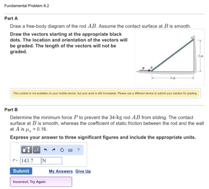
Solved Fundamental Problem 8.2 3 of 4 > Draw a free-body ... Fundamental Problem 8.2 3 of 4 > Draw a free-body diagram of the rod AB Assume the contact surface at B is smooth 3 m P B 4 m Draw the vectors starting at the appropriate black dots. The location and orientation of the vectors will be graded. The length of the vectors will not be graded. 5.7 Drawing Free-Body Diagrams - University Physics Volume 1 Figure 5.32 (a) The free-body diagram for isolated object A. (b) The free-body diagram for isolated object B. Comparing the two drawings, we see that friction acts in the opposite direction in the two figures. Because object A experiences a force that tends to pull it to the right, friction must act to the left. Because object B experiences a component of its weight that pulls it to the left ... (PDF) Solutionmanual 5a | Fatih Demir - Academia.edu Draw the free-body diagram of the crane boom AB has aa weight which has weightofof650 3.25lbkN andand center center of gravity of gravity at G.atThe G. 12 m 3.6 ft The boom boom is supported is supported by abypina pin at Aatand A and cable cable BC.BC. TheThe loadload of B of 6.25 1250 lbkN is suspended is suspended froma acable from cableattached attachedatat B. B. Explain the significance of each force acting on the diagram.
Draw a free-body diagram of the rod ab. assume the contact surface at b is smooth.. Solved Draw a free-body diagram of the rod AB. Assume the ... Draw a free-body diagram of the rod AB. Assume the contact surface at B is smooth. Draw the vectors starting at the appropriate black dots. The location and orientation of the vectors will be graded. The length of the vectors will not be graded. Determine the minimum force P to prevent the 34-kg rod AB from sliding. The contact surface at B is smooth, Free Body Diagram Questions and Answers - Study.com Draw a free body diagram of the ball. View Answer. Earth satellite moves in a circular orbit with an orbital speed of 6200 m/s. (a) Draw a free body diagram for the satellite. (b) Find the time ... (PDF) Book - Mechanical Design 9th Edition | Nasser ... 3 Full PDFs related to this paper. READ PAPER. Book - Mechanical Design 9th Edition Solved Draw a free-body diagram of the rod AB. Assume the ... Transcribed image text: Draw a free-body diagram of the rod AB. Assume the contact surface at B is smooth.b) Determine the minimum force P to prevent the 38-kg rod AB from sliding. The contact surface at B is smooth, whereas the coefficient of static friction between the rod and the wall at A is ?s = 0.22.
Solved Draw a free-body diagram of the rod AB. Assume the ... Assume the contact surface at B is smooth. Draw the vectors starting at the appropriate black dots. The location and orientation of the vectors will be graded. The length of the vectors will not be graded. Determine the minimum force P to prevent the 28-kg rod AB from sliding. The contact surface at B is smooth, whereas the coefficient of static friction between the rod and the wall at A is mu_s = 0.22. PDF Recitation Week 4 Assume the incline is frictionless and take m 1 = 2:00 kg, m 2 = 6:00 kg, and = 55:0 .(a)Draw free-body diagrams of both objects. Find(b)the magnitude of the acceleration of the objects,(c)the tension in the string, and(d)the speed of each object 2:00 s after it is released from rest. m 1 m 2 (a) T m 1g m 1 T N m 2g m 2 Mechanics_Ramkumar_Chapter_03_Equilibrium of ... - FlipHTML5 4] Bar AB of weight W hinged at A and supported by 4]string BD.Prof. Ramkumar's5] Rod Resting inside a sphere 5]6] Bar supported by smooth wall and a peg (nail) 6]7] Bar supported by smooth floor and Edge (Fulcrum) 7]Important points related to F.B.D.(1) Direction of reactions at hinge, roller and fixed supports are arbitrarily assumed in F.B.D ... Solved A) Draw a free-body diagram of the rod AB. Assume ... Engineering. Mechanical Engineering. Mechanical Engineering questions and answers. A) Draw a free-body diagram of the rod AB. Assume the contact surface at B is smooth. B)Determine the minimum force P to prevent the 34-kg rod AB from sliding. The contact surface at B is smooth, whereas the coefficient of static friction between the rod and the wall at A is μs = 0.25.
What is a Free-Body Diagram and How to Draw it (with ... Examples of drawing free-body diagrams. To better understand how to draw free-body diagrams using the 3 steps, let's go through several examples. Example 1. A box is pushed up an incline with friction which makes an angle of 20 ° with the horizontal. Let's draw the free-body diagram of the box. The first step is to sketch what is happening: How to Draw a Free Body Diagram: 10 Steps (with Pictures) Step 1, Identify the body/object you want to make an FBD of. Example: A man is pushing a 10kg box on a rough floor, with a coefficient of friction of µ = 0.6, by applying a 20N force. You will select our body to be the box.Step 2, Draw a simple representation of the body. Example: Make a square to represent the box.Step 3, Think of which forces are acting on the body. Example: These are (1) the weight of the object, (2) the pushing force of the man, (3) the normal force applied by the floor ... PDF Physics 111 Homework Solution #5 friction between each block and the surface is 0.090. • a) Draw a free-body diagram for each block. • b) Determine the acceleration of the system. • c) Determine the tension T in the rope. 6. 0.4. a)Free body diagram for each block b) Projecting Newton's 2nd Law of the two blocks on the y-axis gives: ... The rod rotates along with the ... Mechanics of Materials Tenth Edition in SI Units - Academia.edu Academia.edu is a platform for academics to share research papers.
Engineering Mechanics First Year - SlideShare Find the reactions at the surface of contact A, I and D assuming all smooth surfaces. 9. A 60ON cylinder is supported by the frame- I as shown in figure 4. The frame is hinged D. Determine the reactions developed at .act points A, B, C and D. Neglect the weight of frame and assume all contact surfaces are smooth 19.
Mechanics of Solids S.S. Bhavikatti Pages 51-100 - FlipHTML5 Table 2.2 Free Body Diagrams (FBD) for a Few Typical CasesReacting Bodies FBD required for FBD B a ll W RSm ooth T Smooth Ball R W 600 N 600 N R1 WP Sm ooth Ladder G P R2 T 400 N Block weighing 600 N600 N 600 N R2.13 EQUILIBRIUM OF BODIESA body is said to be in equilibrium when it is at rest or has uniform motion.
programme-mali-nord.de Il y a 1 jour · email protected] [email protected]
PDF Ch 4 Supplemental [ Edit ] - Texas A&M University Draw a freebody diagram for you. Draw the vectors starting at the black dots. The location and orientation of the vectors will be graded. The length of the vectors will not be graded. ANSWER: Ch 4 Supplemental [ Edit ] Overview Summary View Diagnostics View Print View with Answers / LH = = 4.68 N T T
(PDF) Statics and mechanics of Materials - Academia.edu Academia.edu is a platform for academics to share research papers.
12.2 Examples of Static Equilibrium - University Physics ... To set up the equilibrium conditions, we draw a free-body diagram and choose the pivot point at the upper hinge, as shown in panel (b) of (Figure). Finally, we solve the equations for the unknown force components and find the forces. Figure 12.17 (a) Geometry and (b) free-body diagram for the door.
3-INTRODUCTION-TO-EQUILIBRIUM.pptx - Course Hero Free-Body Diagram The following is the general procedure for constructing a free-body diagram. 1. A sketch of the body is drawn assuming that all supports (surfaces of contact, supporting cables, etc.) have been removed. 2. All applied forces are drawn and labeled on the sketch.
PDF ENGINEERING MECHANICS SOLUTIONS - United contact. Ans. Free body diagram of the system is shown as below: Due to symmetry, reactions of A and C on B are same, cos = 50/80 = 51.33° = 90 - 51.33 = 38.7° For equilibrium of B 2 F cos = 100 N Or, F = 64 N 5. A smooth weightless cylinder of radius 600 mm rests on a horizontal plane and is kept from rolling by
Problem 309 | Equilibrium of Concurrent Force System ... Problem 309 A cylinder weighing 400 lb is held against a smooth incline by means of the weightless rod AB in Fig. P-309. Determine the forces P and N exerted on the cylinder by the rod and the incline.
Draw a free-body diagram of the rod AB. Assume the contact ... Draw a free-body diagram of the rod AB. Assume the contact surface at B is smooth. Draw the vectors starting at the appropriate black dots. The location and orientation of the vectors will be graded. The length of the vectors will not be graded. Determine the minimum force P to prevent the 34-kg rod AB from sliding.
PDF Free Body Diagram Exercises - Engineering Example: Free Body Diagrams The roller-band device consists of two rollers, each of radius, r, encircled by a flexible band of negligible thickness and subjected to the two tensions T. Draw the FBD to allow the contact force, R, between the band and the flat supporting surfaces at A and B to be determined. The action is in the horizontal plane
CHAPTER 3 EQUILIBRIUM.pptx - Course Hero Assume the pins at A, B, C, D and the rollers to smooth and frictionless. The rod AB is assumed to be weightless, a statement which although physically Impossible is often used to mean that the weight is negligible when compared with other loads or forces. A B D C 30 ᴼ 7 ft. 3 ft.
5.7 Drawing Free-Body Diagrams - General Physics Using ... Figure 5.32 (a) The free-body diagram for isolated object A. (b) The free-body diagram for isolated object B. Comparing the two drawings, we see that friction acts in the opposite direction in the two figures. Because object A experiences a force that tends to pull it to the right, friction must act to the left. Because object B experiences a component of its weight that pulls it to the left ...
PDF 5 Solutions 44918 - WordPress.com Draw the free-body diagram of the "spanner wrench" subjected to the 20-lb force. The support at A can be considered a pin, and the surface of contact at B is smooth. Explain the significance of each force on the diagram. (See Fig. 5-7b.) A B 6 in. 20 lb 1 in. *5-8. Draw the free-body diagram of member ABC which
Tension, String, Forces Problems with Solutions Problem 1. A block of mass 5 Kg is suspended by a string to a ceiling and is at rest. Find the force Fc exerted by the ceiling on the string. Assume the mass of the string to be negligible. Solution. a) The free body diagram below shows the weight W and the tension T 1 acting on the block. Tension T 2 acting on the ceiling and F c the reaction ...
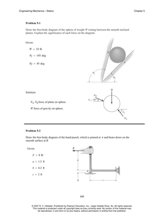
Hibbeler chapter5 - SlideShare Problem 5-2 Draw the free-body diagram of the hand punch, which is pinned at A and bears down on the smooth surface at B. Given: F = 8 lb a = 1.5 ft b = 0.2 ft c = 2 ft 340 © 2007 R. C. Hibbeler. Published by Pearson Education, Inc., Upper Saddle River, NJ.
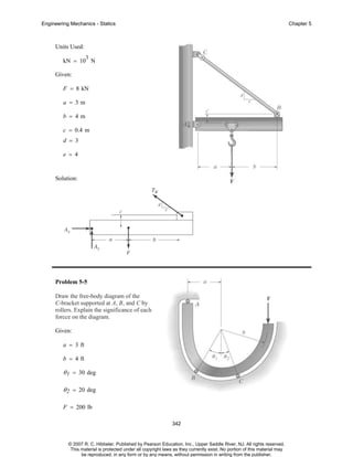
(PDF) Solutionmanual 5a | Fatih Demir - Academia.edu Draw the free-body diagram of the crane boom AB has aa weight which has weightofof650 3.25lbkN andand center center of gravity of gravity at G.atThe G. 12 m 3.6 ft The boom boom is supported is supported by abypina pin at Aatand A and cable cable BC.BC. TheThe loadload of B of 6.25 1250 lbkN is suspended is suspended froma acable from cableattached attachedatat B. B. Explain the significance of each force acting on the diagram.
5.7 Drawing Free-Body Diagrams - University Physics Volume 1 Figure 5.32 (a) The free-body diagram for isolated object A. (b) The free-body diagram for isolated object B. Comparing the two drawings, we see that friction acts in the opposite direction in the two figures. Because object A experiences a force that tends to pull it to the right, friction must act to the left. Because object B experiences a component of its weight that pulls it to the left ...
Solved Fundamental Problem 8.2 3 of 4 > Draw a free-body ... Fundamental Problem 8.2 3 of 4 > Draw a free-body diagram of the rod AB Assume the contact surface at B is smooth 3 m P B 4 m Draw the vectors starting at the appropriate black dots. The location and orientation of the vectors will be graded. The length of the vectors will not be graded.











0 Response to "41 Draw A Free-body Diagram Of The Rod Ab. Assume The Contact Surface At B Is Smooth."
Post a Comment