37 mechanically held contactor wiring diagram
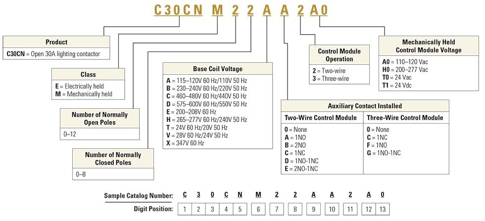
C30CN = Open 30A lighting contactor Class E = Electrically held M = Mechanically held Mechanically Held Control Module Voltage A0 = 110–120 Vac H0 = 200–277 Vac T0 = 24 Vac T1 = 24 Vdc Number of Normally Closed Poles 0–8 Sample Catalog Number: Digit Position: C 3 0 C N M 2 2 A A 2 A 0 123456789 10111213 Control Module Operation 2 = Two ... Feb 16, 2019 · Variety of mechanically held lighting contactor wiring diagram. A wiring diagram is a simplified standard pictorial depiction of an electric circuit. It shows the elements of the circuit as simplified forms, as well as the power and also signal connections in between the gadgets. A wiring diagram normally offers details regarding the relative setting and setup of tools as well as terminals on the tools, to aid in structure or servicing the device.
14.01.2019. 14.01.2019. 3 Comments. on Ge Lighting Contactor Cr460b Wiring Diagram. Results 1 - 48 of 90 NNB GE CRB Lighting Contactor 12 Pole w/v Coil .. There is a k.o. in the front cover for 1 device and wiring diagrams inside the. GE Industrial Solutions CR LIGHTING CONTACTOR SERIES User Manual. Page 4 Wiring Diagrams CRM Mechanically Held ...

Mechanically held contactor wiring diagram
Non-combination C30CN Electrically and Mechanically Held ... Wiring Diagrams . ... Class ECC04 — Non-combination Mechanically Held Lighting Contactor ... Eaton contactor wiring diagram lovely wiring diagram contactor. Mechanically held lighting contactors from eatons electrical sector are designed for industrial commercial and outdoor lighting applications where efficient control is required. Switch it off from the systems circuit breaker. ASCO 918 Lighting Contactors Drawing & Wiring Diagrams Drawing and Wiring Diagrams Typical wiring diagrams for Standard and accessory control situations Standard Wiring Accessory 47 Two Wire Control. Accessory 48 Three Wire Control! Accessory 49 Stop/Start Control ! RC CONTROL CONIRCL MCDU1f CON 1 Rot . c.cWROL CONTROL MODULE
Mechanically held contactor wiring diagram. electrically held contactors require a constant current and a constant power dissipation to hold the circuit. a common relay or motor starter is a good example of this type of contactor. a mechanically held contactor is held in place without the need of a constant power drain. the coil on these type of contactors is far less likely to burn up ... Problem: AC electrically held contactors are buzzing when energized. Noise is loud enough to be objectionable. Solution: See MDshunk's EXCELLENT post describing the use of the ice cube relay, interval timers and mechanically held contactors. It would take very little time and effort to wire up and will solve the problem. Electrically Held to Mechanical Latch Contactor • Retrofit Instructions 5 1502-IN001%-EN-P – -XQH Install the Mechanically Latched Auxiliary Contact Assembly 1. Wire the closing and trip coils to the Mechanically Latched auxiliary contact assembly as shown in the diagram below: Figure 6 – Auxiliary Contact Assembly Layout 2. Ge lighting contactor cr460 wiring diagram. Ge lighting contactor cr460 wiring diagram ge control catalog section 3 74951. Here is a picture gallery about mechanically held lighting contactor wiring diagram complete with the description of the image please find the image you need. Many large pieces of. Source: hanenhuusholli.blogspot.com
Lighting Contactor Schematic - 9 images - lighting circuits connections for interior electrical, photocell light switch wiring diagram electrical circuit, Mechanically held lighting contactor wiring diagram. Class lc electrically held lighting contactors convertible to mechanically held features 8 catalog numbering system 9 selection 10 11 technical data 12 accessories factory mods and replacement parts 13 16 dimensions 17 21 wiring diagrams 22 24 contents class clm mechanically held lighting contactors are. 3-16 Modified assembled forms - electrically held 3-18 Lighting contactors CR463M 3-18 Standard assembled forms 3-20 Modified assembled forms - mechanically held 3-22 Lighting contactors CR460, CR463 3-22 Technical data 3-23 Lighting contactors CR463L, CR463M 3-23 Wiring diagrams 3-24 Outlines and dimensions for estimating only Dec 10, 2017 · Wiring Diagram For Mechanically Held Contactor. Cr460 series revision 11 021402 c30cn lighting contactors instruction sheet contactorotor starters if 1698 xlc explosionproof i have a master electrician working on my house but he has never installed mechanically held square d 8903 lx ge solutions contactor user manual page 4 class type 2 thru 12 ...
Nov 14, 2004 — I am looking for help or possibly a diagram on how to connect a mechanically held lighting contactor to a photocell. Ge Lighting Contactor Cr460 Wiring Diagram. GE CR Series Lighting Contactors Contact position indication - when button protrudes, two #8 AWG wires A simple kit easily converts electrically held units to mechanically held and . FIELD WIRING DIAGRAM VAC THREE PHASE . GE's new CR Series lighting contactors deliver unprecedented versatility in .. Sep 13, 2021 · Mechanically held lighting contactor wiring diagram. Here is a picture gallery about mechanically held lighting contactor wiring diagram complete with the description of the image please find the image you need. The wa4 mechanical latching unit for af tactors can be easily converted into compact latched contactors. Class Type S multipole lighting contactors are available as electrically held or mechanically held devices and can be ordered as Schneider Eletric Square D Picture Wiring Diagram Book, 7/14/18, English, CTpdf MB. I have a LXG lighting contactor and need the wiring diagram for this. where do i go to get this? I can get my - Square D 30 Amp Lighting.
It has been a time!. I need you to verify some things for me ...
Mechanically Held 30 Ampere Lighting Contactors Application Guide AP03702001E Effective February 2006 Overview C30CNM Mechanically Held Lighting Contactors feature an electronic control module that allows coil operation at line voltage and control at the same voltage or at a different voltage.

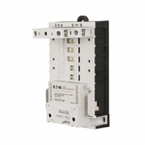
Eaton- How to convert the C30CN lighting contactor from electrically held to mechanically held
FEEDBACK loop from NC auxiliary contact ensures proper coordination between contactor status and control command. FIGURE 3. 2-WIRE CONTROL WIRING — TWO SOURCES.

Square D 8903LXO1000V02 110/120 VAC 30 Amp 10-Pole 10NO Open Type Mechanically Held Lighting Contactor
Abb Cr460xmn Lighting Contactor Conversion Kit Electrically Mechanically Held Rexel Usa. Ge Lighting Magnetic Contactor 120v Ac Coil Volts Type Electrically Held Number Of Poles 3hya1 Cr463l40aja Grainger. Ge Cr460xp32 2 Pole Power For Cr460 Series Lighting Contactor Newegg Com.

Eaton IF 1698 - XLC Explosionproof Lighting Contactors ...
Conversion kits for mechanically held contactors Kits for converting an electrically held contactor to a mechanically held version. Kits includes control module, latch, latch cover and auxiliary contact(s) plus installation instructions. Conversion kits are suitable for coil voltages 277 V and below. Use CPT to reduce coil voltage if line voltage

Volume 10 Tab 4
contactor is operated from a momentary pilot device and requires an auxiliary contact tobe used as a holding interlock. • 2-wire control is used for single location control with power continuously supplied to thecoil for contactor operation. CR463M Mechanically Held Contactors

I have a Master Electrician working on my house but he has ...
Wiring Diagram (Electrically Held Contactor) Refer to control module instruction sheets for wiring of mechanically held contactors. Class LC Electrically Held Lighting Contactor (Convertible to Mechanically Held) Catalog numbers LCE00C* Page 5 of 6 Notes: 1. Refer to the NEC or local electric code as required. 2.
30CN mechanically held lighting contactors | Eaton
Siemens Industry Catalog - Low-Voltage controls and distribution - NEMA & General Purpose Controls - Lighting Control - Mechanically Held Contactors, Class CLM & CM. Login Login. As an already registered user simply enter your userame and password in the login page in the appropriate fields. ...

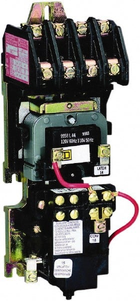
SOLVED: I have a 8903 LXG lighting contactor and need the - Fixya
the coil for contactor operation. CR463M Mechanically Held Contactors A mechanical latch with a 2- or 3-wire electronic control module delivers reliable performance and protection from such application abnormalities as line noise, leakage currents from controller outputs, or short repetitive commands burst from faulty controllers. Mechanical ...
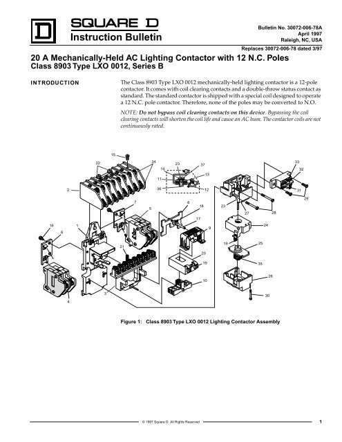
Instruction Bulletin - Schneider Electric
table c: 3-wire connection diagram c electronic p1 p2 a1 p3 p4 module p5 a2 control voltage n p p coil n voltage 3 3 p1 p2 p3 p4 p5 electronic module c a2 a1 c fuse 2 fuse coil voltage 2 off g on r cc p n off on p1 p2 p3 p4 p5 a1 c fuse coil voltage 2 cc p hand off auto table b: optional wiring and pilot devices for mechanically-held contactor, 2-wire control off-on off-auto selector switch
Contactor As An Important Part Of The Motor Control Gear | EEP
Wiring Terminals. Class Type S multipole lighting contactors are available as electrically held or mechanically held devices and can be ordered as Schneider Eletric Square D Picture Wiring Diagram Book, 7/14/18, English, CTpdf MB. Class / Refer to Catalog CT Square D panelboards; short- circuit ratings to kA; Table Class Type PB Lighting ...

How to convert the C30CN lighting contactor from electrically ...
Dec 10, 2017 · Wiring Diagram Book Schneider Electric. Instruction Bulletin Schneider Electric. Contactorotor Starters. Square D 8903spo11v02 110 120 Vac 60 Amp 3 Pole Open Type Mechanically Held Lighting Contactor Cooper Electric. Selecting Effective Lighting Control White Paper. Square D 8903lo20v02 Province Electric Supply.
Electrically Held to Mechanically Latched Contactor
Installation Sheet. Square D 8903lx01200v02 30a Lighting Contactor Mechanically Held Type Ul 600vac Rated Open Enclosure 12 Poles. Lighting Contactors General Purpose Siemens Usa. 8903spo11v02 Contactor Type S Multipole Lighting Mechanically Held 60a 3 Pole 110 120 Vac 50 60 Hz Coil Open Style Schneider Electric Usa.
Cutler-Hammer C30CNE20A0 | Turtle & Hughes
ASCO 918 Lighting Contactors Drawing & Wiring Diagrams Drawing and Wiring Diagrams Typical wiring diagrams for Standard and accessory control situations Standard Wiring Accessory 47 Two Wire Control. Accessory 48 Three Wire Control! Accessory 49 Stop/Start Control ! RC CONTROL CONIRCL MCDU1f CON 1 Rot . c.cWROL CONTROL MODULE
Has anyone wired this kind of lighting contactor with a ...
Eaton contactor wiring diagram lovely wiring diagram contactor. Mechanically held lighting contactors from eatons electrical sector are designed for industrial commercial and outdoor lighting applications where efficient control is required. Switch it off from the systems circuit breaker.
CR460 series Revision 11 021402
Non-combination C30CN Electrically and Mechanically Held ... Wiring Diagrams . ... Class ECC04 — Non-combination Mechanically Held Lighting Contactor ...

Contactors and Motor Starters

GRay again. What would make a mechanically held latch and ...

SQD 8903SQO11V02

Siemens CLM62031 110/120 VAC 20 Amp 6-Pole 6NO Open Mechanically Held Lighting Contactor

CN35DN3 CUTLER HAMMER LIGHTING CONTACTOR

Motor Control Center Design Guide 600V | PAKTECHPOINT

GE 463MD0CJD Lighting Contactor Mechanically Held 30A NEW ...
Volume 10 Tab 4

Square D 8903SPO11V02 110/120 VAC 60 Amp 3-Pole Open Type Mechanically Held Lighting Contactor

SQD 8903LXO80V02
Selecting Effective Lighting Control White Paper
500LC Mechanically Held Multi-Pole Lighting Contactors ...
Introduction Contactor Components
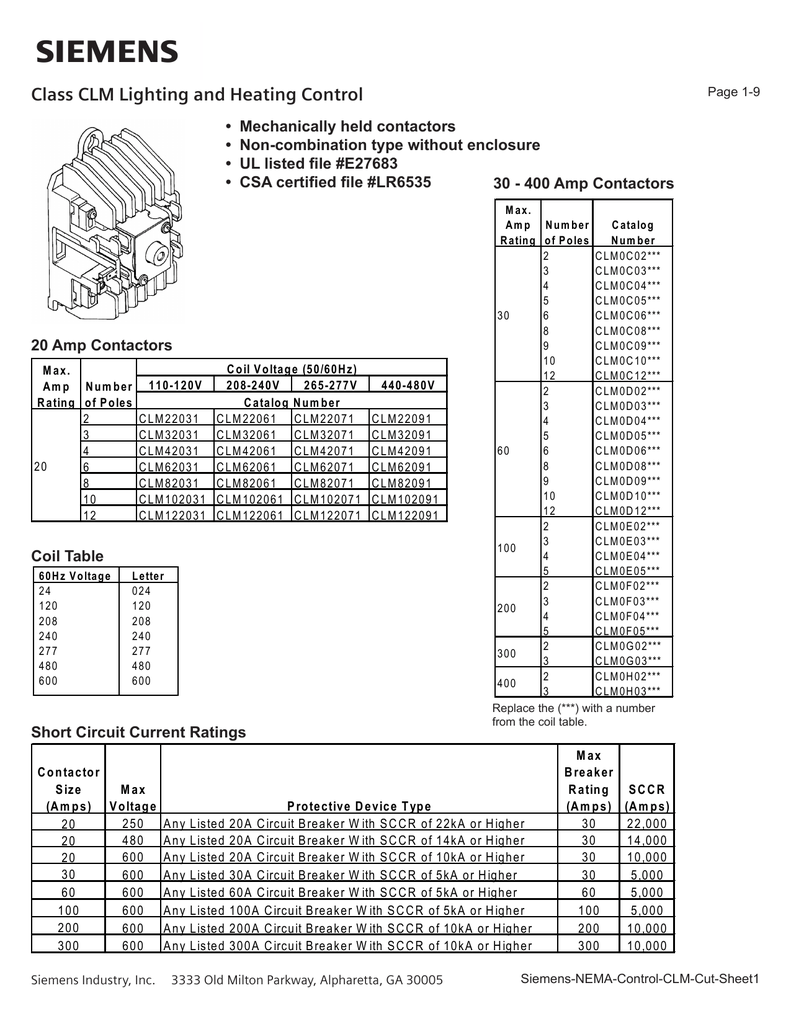
Class CLM Lighting and Heating Control
Square D - No Enclosure, 4 Pole, Mechanically Held Lighting ...
Lighting Contactors

Amazon.com: 60Amp NC Lighting Contactor 4 Pole (NC) Normally ...

GE CR463M60DNA14B0 MECHANICALLY Held 6p Lighting Contactor ...

SOLVED: I have a 8903 LXG lighting contactor and need the - Fixya

Class 8903 Type LX Mechanically Held Lighting Contactor 2 ...

Contactors (Control Pilot Devices)
Square D - No Enclosure, 2 Pole, Electrically Held Lighting Contactor - 69666527 - MSC Industrial Supply
0 Response to "37 mechanically held contactor wiring diagram"
Post a Comment