42 fe-fe3c phase diagram
Non‐noble electrocatalyst for the oxygen evolution reaction (OER) is essential for water electrolysis and electrochemical conversion of CO 2 . Integrating electrochemical fixation of CO 2 and electrochemical metallurgy to prepare advanced OER electrocatalyst is a promising solution to promote carbon neutrality and renewable energy. Herein, the electrochemical reduction of CO 2 and Fe 2 O 3 are combined in molten salts to prepare cathodic Fe 3 C‐based electrocatalyst and anodic oxygen at 600 °C w... A ChemE freshman here, needing help. Would like to plot on screen first so my worksheet would be neat. Thanks!!
This sceencast is part four of our series about phase diagrams. This sceencast is focused on addressing issues students have with Iron-Iron Carbide (Steel) E...

Fe-fe3c phase diagram
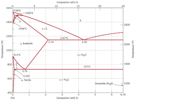
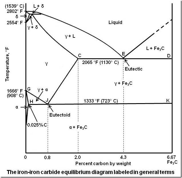
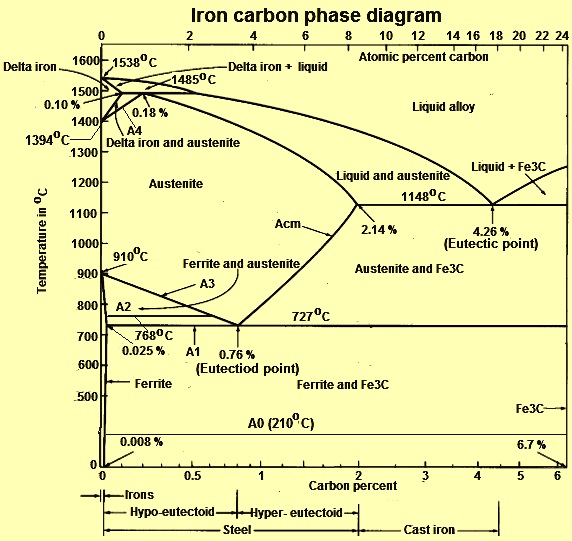
Fe-Fe3C is not considered an equilibrium phase diagram, because Fe3C is behaving metastable in iron. It is not really a metallurgical reason but a thermochemical reason, in an equilibrium phase diagram, there are no metastable phases. Iron carbide (Fe 3 C) is often labeled as the uncorroded portion of the steel. It is primarily associated with mild steels having a high carbon content and a ferritic-pearlitic microstructure. During corrosion of such steel, the ferrite phase dissolves and a porous iron carbide network is exposed (see Fig. 7.6).Given that iron carbide is an electronic conductor, this porous network serves as ... In the figure, there is the iron–iron carbide (Fe–Fe3C) phase diagram. The percentage of carbon present and the temperature define the phase of the iron carbon alloy and therefore its physical characteristics and mechanical properties. The percentage of carbon determines the type of the ferrous alloy: iron, steel or cast iron. Source: wikipedia.org Läpple, Volker – Wärmebehandlung …
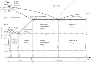
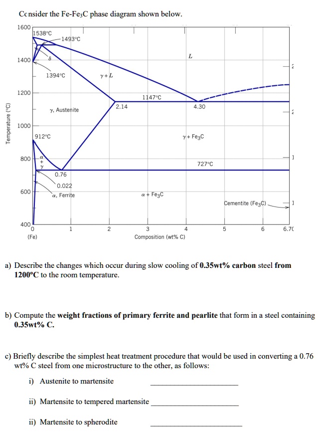
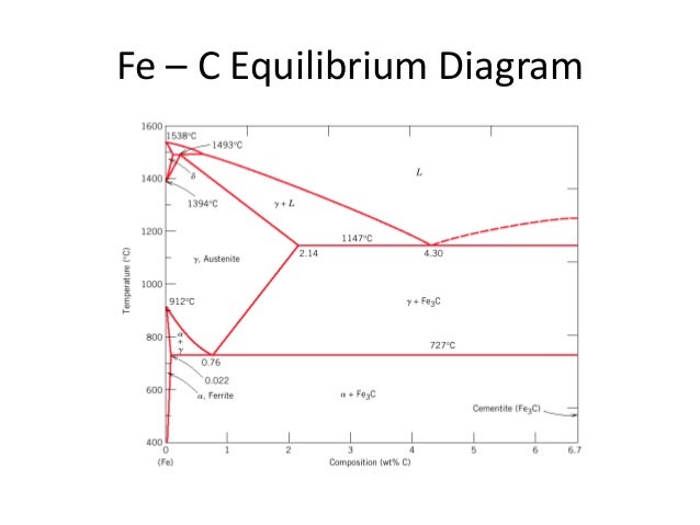
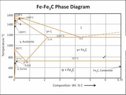
Fe-fe3c phase diagram. The Iron ‐ Iron Carbide (Fe‐Fe3C) Phase Diagram Reactions Phases Present Peritectic L + δ = γ Lat T=1493oC and 0.18wt%C δ ferrite delta Eutectic L = γ + Fe3C Bcc structure at T=1147oC and 4.3wt%C Paramagnetic Eutectoid γ = α + Fe3C γ austeniteat T=727oC and 0.77wt%C Fcc structure Non‐magnetic ductileMax. solubility of C α ferrite Fe3C cementitein ferrite=0.022% Bcc structure ... Foundations of Materials Science and Engineering (5th Edition) Edit edition Solutions for Chapter 9 Problem 2P: (a) Why is the Fe-Fe3C phase diagram a metastable phase diagram instead of a true equilibrium phase diagram? (b) Define the following phases that exist in the Fe-Fe3C phase diagram: (i) austenite, (ii) α ferrite, (iii) cementite, (iv) δ ferrite. 31.10.2016 · Wang, J. et al. Synthesis of Fe/Fe3C nanoparticles encapsulated in nitrogen-doped carbon with single-source molecular precursor for the oxygen reduction reaction. Carbon 75 , 381–389 (2014). Answered 6 years ago The figure above shows a typical Fe-Fe3C phase diagram. Case 1: For composition range between 0.022 and 0.76 (Hypo-eutectoid steel) When we come down from a temperature of 1000 degrees to say 600 degrees, the order of phases are γ ,Austenite ------ ( α ,Ferrite + γ )------- ( α + F e 3 C), Pearlite.
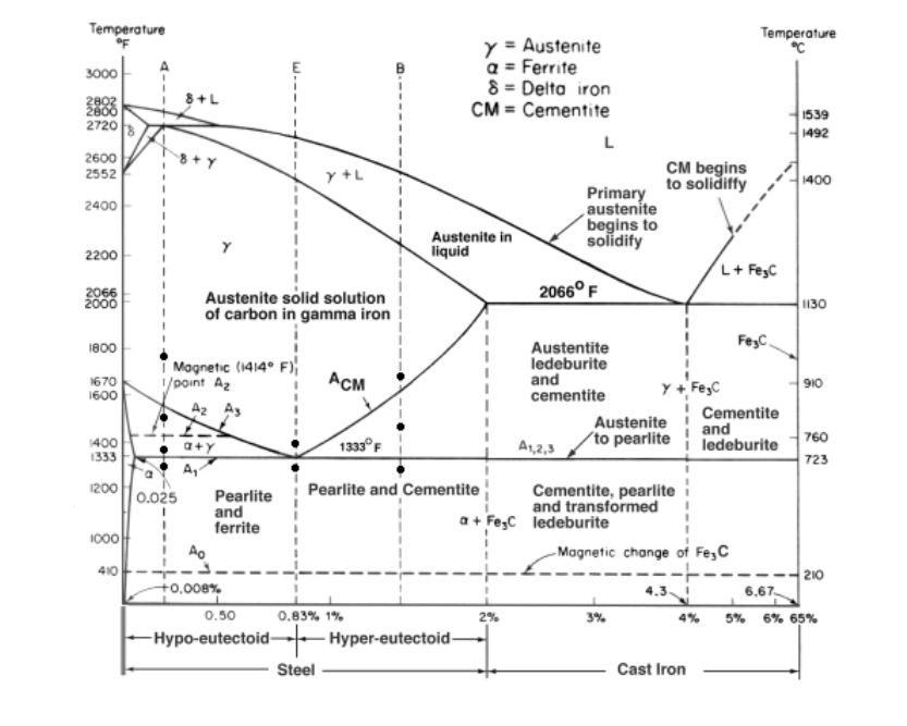
The graph is quite complex but since we are limiting our exploration to Fe3C, we will only be focusing up to 6.67 weight percent of carbon. This iron carbon phase diagram is plotted with the carbon concentrations by weight on the X-axis and the temperature scale on the Y-axis. Iron crystal structures explained In a heterogeneous Fenton‐type FeN x /C catalyst, Fe‐N x sites and graphene‐encapsulated Fe/Fe3C nanoparticles promote the efficient generation of hydroxyl radicals from H2O2 for the highly selective oxidation of methane to formic acid. The reaction mechanism at the active sites has been studied. Abstract -------- H2O2 as a well‐known efficient oxidant is widely used in the chemical industry mainly because of its homolytic cleavage into .OH (stronger oxidant), but this reaction always comp... Iron-Carbon Phase Diagram with Detailed Explanation: If the percentage of the carbon is in the range of 0 to 2.11 % then it is called Steel and if the percentage of carbon is in the range of 2.11 to 6.67% then it is called Cast iron. As the carbon content increases, it produces more Iron-Carbide volume and that phase will exhibit high hardness. H 2 O 2 as a well‐known efficient oxidant is widely involved in chemical industry mainly because of its homolytic cleavage into •OH (stronger oxidant), but it always competes with O 2 generation resulting in H 2 O 2 waste. Here, we fabricate heterogeneous Fenton‐type Fe‐based catalysts containing Fe‐N x sites and Fe/Fe 3 C nanoparticles as a model to study this competition. Fe‐N x at the low spin state is the active site for •OH generation. Fe/Fe 3 C, especially for Fe 3 C, promotes Fe‐N x sites...
This is part three in a series of screencasts about phase diagrams. This video introduces major features of the Fe-Fe3C phase diagram, steel classification, ... PHASE TRANSFORMATION Liquid to Austenite •Eutectic transformation-1148C, •C-2.11%-4.3% •Eutectic transformation-4.3% C, 1148C •Eutectic transformation L-γ+F (Fe) C, wt%C 1148ºC T(ºC) a Adapted from Figs. 9.24 and 9.32,Callister & Rethwisch 8e. (Fig. 9.24 adapted from Binary Alloy Phase Diagrams, 2nd ed., Vol. 1, T.B. Massalski (Ed.-in-Chief), ASM International, Materials Park, OH, 1990.) (Fe-C System) 6 C 0 Fe 3 C g g g g g g g g g g g Adapted from Fig. 9.33, Callister & Rethwisch 8e ... I’d like to wire one of my guitars with 2 humbuckers with a volume and tone for each, a 3 way pickup selector switch, a 2 way switch to go out of phase, and a 2 way switch to split the coils. Like the wiring on the frank zappa Roxy SG.
The Iron Carbide (Fe Fe3C) Phase Diagram - UPRM Pages 1-50 ...
In a heterogeneous Fenton‐type FeN x /C catalyst, Fe‐N x sites and graphene‐encapsulated Fe/Fe3C nanoparticles promote the efficient generation of hydroxyl radicals from H2O2 for the highly selective oxidation of methane to formic acid. The reaction mechanism at the active sites has been studied. Abstract -------- H2O2 as a well‐known efficient oxidant is widely used in the chemical industry mainly because of its homolytic cleavage into .OH (stronger oxidant), but this reaction always comp...
The Iron - Iron Carbide (Fe-Fe C) Phase Diagram
11.03.2013 · The iron –carbon phase diagram in Fig 2 actually shows two diagrams namely (i) the stable iron-graphite diagram (red lines), (ii) and the metastable Fe-Fe3C diagram. Cementite is metastable, and the true equilibrium is to be between iron and graphite (C). Although graphite occurs extensively in cast irons, it is usually difficult to obtain this equilibrium phase in steels. …

File:Fe-C diagram.png - Wikimedia Commons
1. Solid phases in the Fe-Fe3C phase diagram: Four solid phases, namely α-Ferrite,. Austenite, Cementite (Fe3C), and δ ...
What is Common Phases in Steels - Definition | Material ...
... students have about iron- iron carbide phase diagram microstructures. ... Muddiest Point- Phase Diagrams V: Fe-Fe3C Microstructures.
Analysis of Carbon–iron (Fe–Fe3C) Phase Diagram 1. Experimental
https://imgur.com/a/x8XS0si What's the striped line? And what's up with the L (liquid) and glass? Something can't be glass and liquid simultaneously.
Solved From the Fe-Fe3C phase diagram below, answer the ...
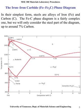
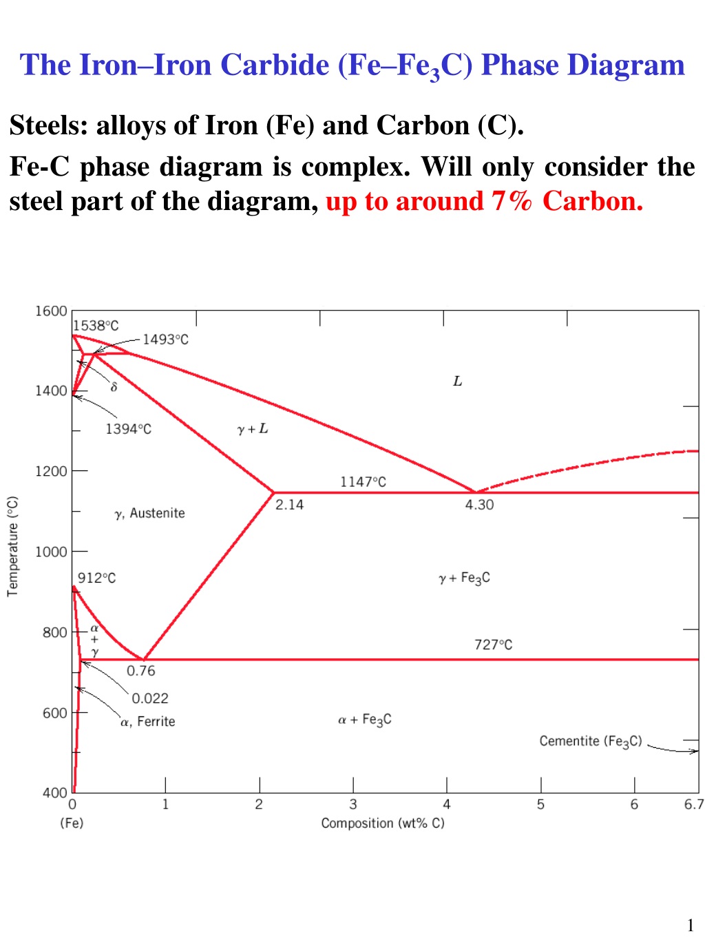
Fe-C diagram. 1. The Iron-Carbon Phase Diagram Prof. H. K. Khaira Professor in MSME Deptt. MANIT, Bhopal. 2. Iron-Carbon Phase Diagram • In their simplest form, steels are alloys of Iron (Fe) and Carbon (C). • The Fe-C phase diagram is a fairly complex one, but we will only consider the steel and cast iron part of the diagram, up to 6 ...
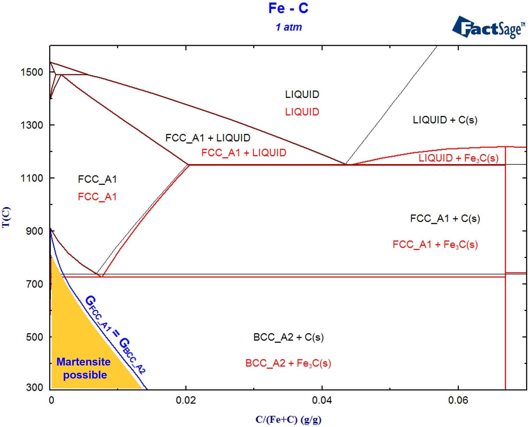
Example for a FactSage calculation of a non-equilibrium ...
Oct 14, 2018 · The iron–iron carbide (Fe–Fe3C) phase diagram describes the iron-carbon system of alloys containing up to % of carbon, discloses the phases compositions and their transformations occurring with the alloys during their cooling or heating. 4 Hypereutectoid alloys Hypereutectoid steel: has a carbon content greater than the eutectoid 8 Example: Phase Equilibria For a wt% Fe wt% C at a temperature just.Iron-Iron Carbide Phase Diagram ExamplePhase diagram - Wikipedia
Microstructure formation of steels during solidification ...
Review Fe-C phase diagram The influence of other alloying elements REutectoid changes. 6 Summary. 1000 700 ("t % C) ite 1000 700 500 400 72700. Fe3C 2.0 1.0 Composition (wt% C) a 0.022 C'o U Fe3C a + Fegc 6.70 Composition (wt% C) 0.76 . 0.8 0.6 0.4 0 0.2 10 12 Concentration of alloying elements (wt%) 1200
Fe-Fe3C T-T-T Diagram | Metallurgy for Dummies
Fig 1: Fe-Fe3C Phase Diagram (clickable), Materials Science and Metallurgy, 4th ed., Pollack, Prentice-Hall, 1988 Figure 1 shows the equilibrium diagram for combinations of carbon in a solid solution of iron. The diagram shows iron and carbons combined to form Fe-Fe3C at the 6.67%C end of the diagram. The left side of the diagram is pure iron ...

basic material knowledge for Mechanical engineer : Carbon ...
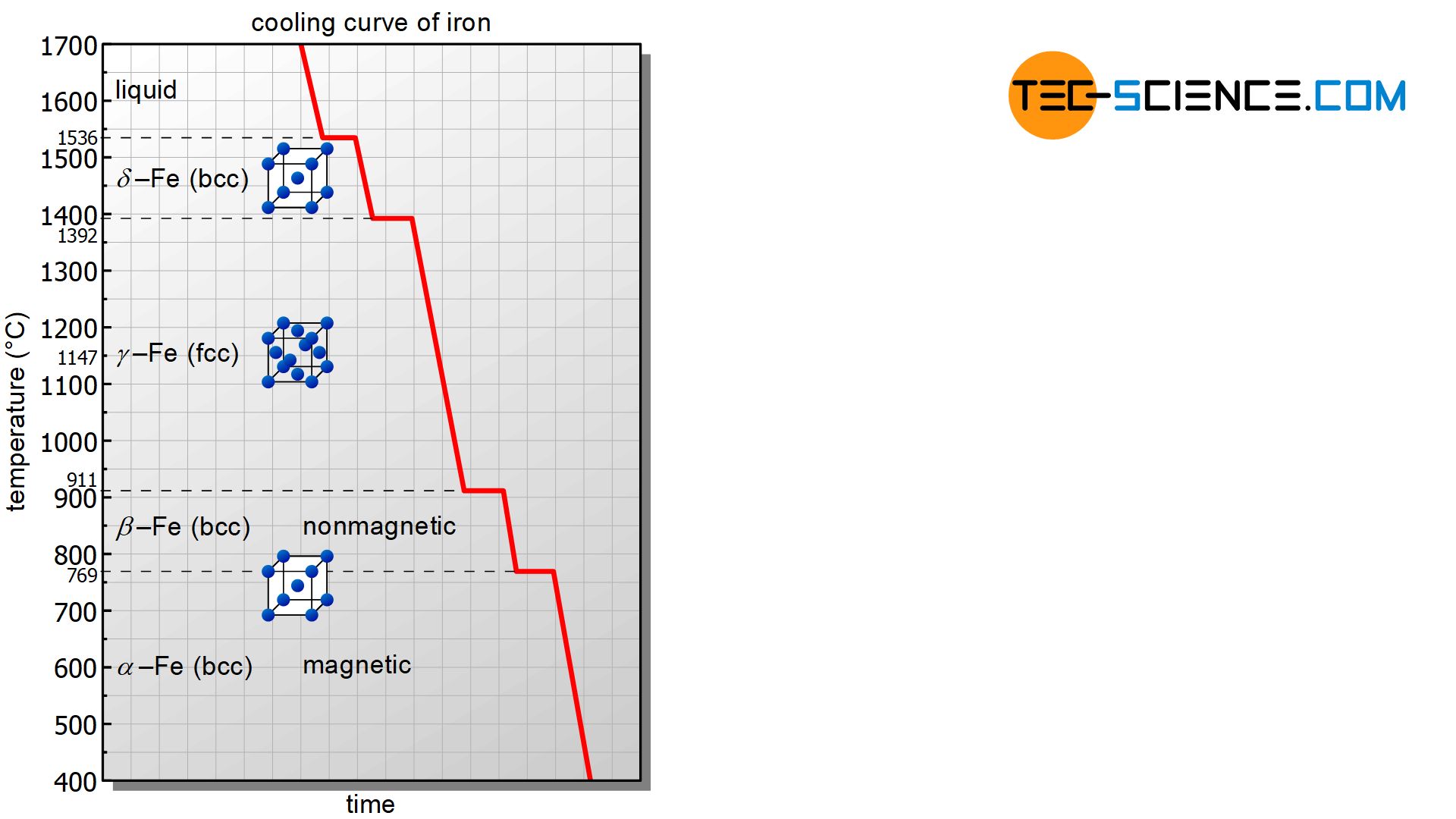
C Phase Diagram. ➢ α-ferrite - solid solution of C in BCC Fe. • Stable form of iron at room temperature. • Transforms to FCC g-austenite at 912 °C.
Solved The iron-iron carbide (Fe-Fe3C) phase diagram is ...
Download scientific diagram | Fe-Fe3C Phase Diagram with approximate carbon levels of HSLA (green), DP (pink) and TRIP (blue) [9]. from publication: ...
Fe–C System. Stable and Metastable Equilibrium Diagrams ...
Jul 08, 2020 · What is Fe-Fe3C phase diagram? The Fe-C phase diagram is a fairly complex one, but we will only consider the steel part of the diagram, up to around 7% carbon. α-ferrite – solid solution of C in BCC Fe • Stable form of iron at room temperature. The maximum solubility of C is 0.022 wt%. Transforms to FCC γ-austenite at 912 °C.

The Iron Carbon Phase Diagram
The Fe-C phase diagram is a fairly complex one, but we will only consider the steel part of the diagram, up to around 7% carbon. Page 2. Phases in Fe–Fe3C Phase ...
Iron-Carbon Phase
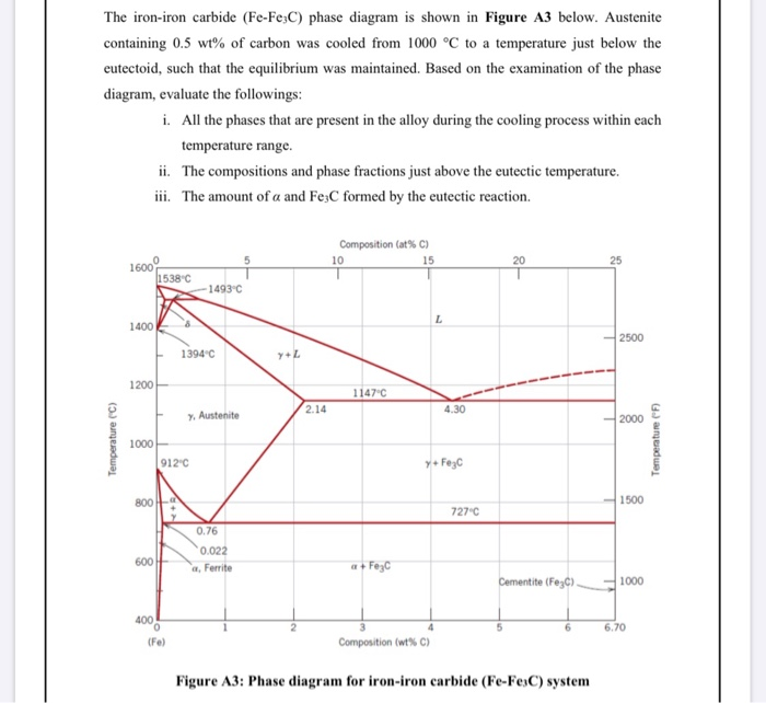
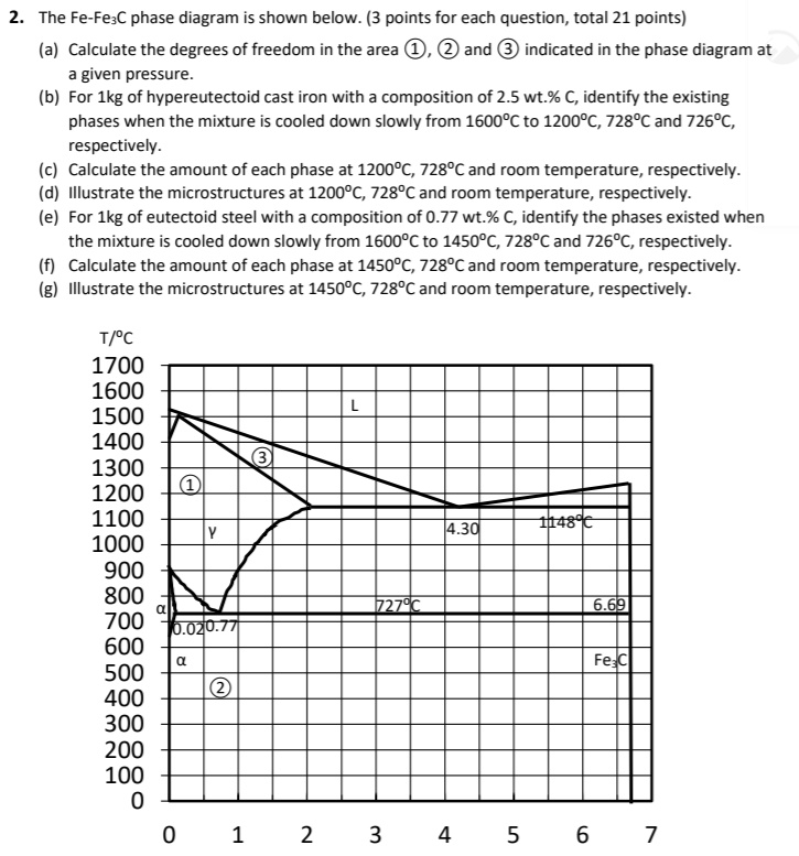
Phase Equilibria Solution: 94.3 g Fe C 5.7 g 100 5.7g 6.7 0.022 0.4 0.022 x100 Fe C Fe C 3 3 Fe C 3 3 α= = = − − = − − = +α α α x C C Co C b) the amount of carbide (cementite) in grams that forms per 100 g of steel a) composition of Fe 3C and ferrite (α) C O = 0.40 wt% C Cα= 0.022 wt% C C Fe C = 6.70 wt% C 3 Fe 3 C (cementite) 1600 1400 1200 1000 800 600 400 0 12 3 4 5 66.7 L γ

The Iron Carbide (Fe Fe3C) Phase Diagram - UPRM - Flipbook by ...
Phase Diagrams 148–177 7.1 The Phase Rule 148 7.2 Single-component Systems 150 7.3 Binary Phase Diagrams 151 7.4 Microstructural Changes during Cooling 157 7.5 The Lever Rule 159 7.6 Summary of Phase Diagram Rules 161 7.7 Some Typical Phase Diagrams 163 7.8 Other Applications of Phase Diagrams 170 Summary 171 Problems 171 Multiple Choice Questions …
Practical Maintenance » Blog Archive » The Iron-Iron Carbide ...
Fe-Fe3C phase diagram The phase diagram is made up of a number of phase boundaries. As was have seen in the last part of Tutorial 7 , these boundaries can be found by finding a point on the boundary, then tracing the boundary as a function of element content.

The Iron Carbide (Fe Fe3C) Phase Diagram - 2008-01-11nose of ...
I am getting confused with this theory, is there any better way to remember or to watch some videos to clear out the concepts. I would appreciate your help. Thanks
What is the use of an iron carbide phase diagram? - Quora
Martensite is not shown in the equilibrium phase diagram of the iron-carbon system because it is not an equilibrium phase. Equilibrium phases form by slow cooling rates allowing sufficient time for diffusion, whereas martensite is usually formed by fast cooling rates. Since chemical processes (the attainment of equilibrium) accelerate at higher temperature, martensite is easily …

SOLUTION: Fe Fe3C Phase Diagram Presentation - Studypool
C Phase Diagram ¾α‐ferrite‐ ... o Phase transformations between phases with different densities Annealing temperatures are relatively low so that useful effects of cold working are not eliminated. Examples of heat treatment • Lower critical temperature A 1 below which austenite does not exist • Upper critical temperature lines, A 3 and A cm above which all material is austenite ...
Iron–Iron Carbide (Fe–Fe3C) Phase Diagram
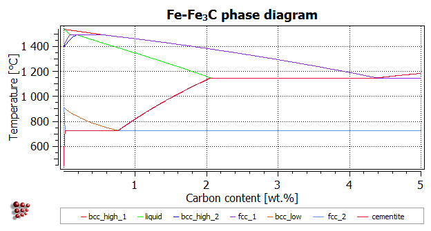
In the present evaluation, the assessed stable Fe-C (graphite) and metastable Fe-Fe3C (cementite) equilibrium phase diagrams for 0 to 25 at.% C are based on thermodynamic calculations reported by [79Schl] and [84Oht].

iron carbon phase diagram
It showed all their developmental products
Fe-Fe3C phase diagram of common S235JR construction steel ...
The Fe-Fe 3 C binary phase diagram under high magnetic fields up to 21 T was investigated by a differential thermal analysis. Applying a magnetic field of 18 T, the α-γ transformation temperature T α-γ for pure iron increased quadratically from 1181 K (a zero field) to 1206 K. With increasing magnetic field strength, the transformation temperature A c1 (α-Fe + cementite → α-Fe + γ ...

1. Given the Fe-Fe3C phase diagram, calculate the | Chegg.com
In presented paper the algorithm for Fe-Fe3C phase diagram calculation and developed computer program, PD_Fe_Fe3C are presented. Results of calculations using this program were compared with date ...
Iron Carbide – IspatGuru
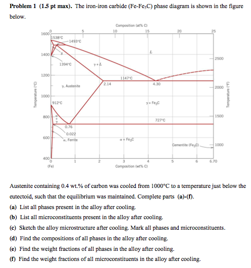
Mechanical Engineering questions and answers. Consider the following Fe-Fe3C phase diagram. The phase (s) present in a steel alloy containing 3 wt% Cat a temperature T = 1200°C are: Ibu 1538"C 1493'C 1400 2500 1394C +L 1200 1147C 2.14 4.30 Austenito 2000 Temperature ("C) Temperature (°F) 1000 912"C y + Fegc 1500 800 727'C > 0.76 0.022 600 a ...

15. From the iron-carbon phase diagram (see Figure below) a ...
Fe – Fe3C Phase Diagram 5. Fig 1 Iron Carbon phase diagram. The diagram shown in Fig 1 actually shows two diagrams i) the stable iron-graphite diagram (dashed lines) and the metastable Fe-Fe3C diagram. The stable condition usually takes a very long time to develop specially in the low temperature and low carbon range hence the metastable ...

Materials Science: Tutorials
i.e. is the crystal structure of a hypothetical γ″ phase in iron the same as in manganese? Or might one be BCC and the other HCP? New to metallurgy

Fe -Fe 3 C phase diagram (a) and range of homogeneity of ...
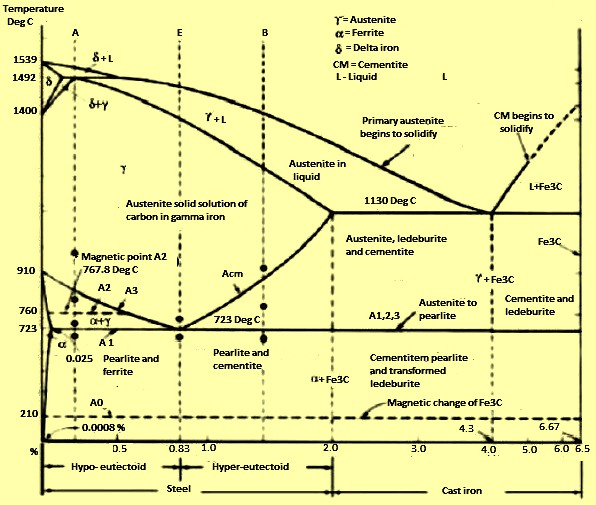
ADVERTISEMENTS: The Iron-Iron carbide (Fe-Fe3C) is defined by five individual phases and four invariant reactions. Five phases are- α-ferrite (BCC) Fe-C solid solution, γ-austenite (FCC) Fe-C solid solution, δ -ferrite (BCC) Fe-C solid solution, Fe3C (iron carbide) or cementite – an inter- metallic compound and liquid Fe-C solution. Four invariant reactions are eutectoid, eutectic ...
SOLVED:Ccnsider the Fe-Fe3C phase diagram shown below_ 600 ...
Answered 6 years ago The figure above shows a typical Fe-Fe3C phase diagram. Case 1: For composition range between 0.022 and 0.76 (Hypo-eutectoid steel) When we come down from a temperature of 1000 degrees to say 600 degrees, the order of phases are γ ,Austenite ------ ( α ,Ferrite + γ )------- ( α + F e 3 C), Pearlite.
fe-c diagram
A very important phase change in the metastable Fe-C phase diagram occurs at 0.68 wt. % C. The transformation is eutectoid, and its product is called pearlite (ferrite + cementite) : gamma-iron (austenite) —> alpha-iron (ferrite) + Fe3C (cementite). Some important boundaries at single-phase fields have been given special names. These include :
Iron Carbide
Draw Fe Fe3C diagram and explain Euctetoid, Eutectic and Peritectic transformations in Fe Fe3C. written 5.5 years ago by juilee ♦ 8.5k ... Liquid-100 wt% →51.97wt% γ +Fe3C (48.11wt%) The phase mixture of austenite and cementite formed at eutectic temperature is called ledeburite.
Solved In the Fe-Fe3C phase diagram, answer the | Chegg.com
Answer: Iron loses its magnetic nature at 1043K and early investigators found that this loss is due to phase transformation and named the paramagnetic iron( above 1043K) as beta iron.Later it was found that the loss in magnetic nature is not because of phase transformation and they removed the be...

MatCalc Homepage
Fe-Fe 3 C T-T-T Diagram, Adapted from Callister pg. 295, Fig. 10.6 The time-temperature transformation curves correspond to the start and finish of transformations which extend into the range of temperatures where austenite transforms to pearlite. Above 550 C, austenite transforms completely to pearlite.
Muddiest Point- Phase Diagrams III: Fe-Fe3C Phase Diagram Introduction
Transformations and Microstructures of Slowly Cooled Steels in Fe-Fe 3 C Equilibrium Diagram: In Fe-Fe 3 C diagram (Fig. 1.22), ABCD is a liquidus, above which every alloy is in liquid state. AOPQCRD is a solidus below which every alloy is completely solid.
APPLICATIONS OF Fe-C PHASE DIAGRAM
In the figure, there is the iron–iron carbide (Fe–Fe3C) phase diagram. The percentage of carbon present and the temperature define the phase of the iron carbon alloy and therefore its physical characteristics and mechanical properties. The percentage of carbon determines the type of the ferrous alloy: iron, steel or cast iron. Source: wikipedia.org Läpple, Volker – Wärmebehandlung …
Solved The iron-iron carbide (Fe-Fe3C) phase diagram is ...
Iron carbide (Fe 3 C) is often labeled as the uncorroded portion of the steel. It is primarily associated with mild steels having a high carbon content and a ferritic-pearlitic microstructure. During corrosion of such steel, the ferrite phase dissolves and a porous iron carbide network is exposed (see Fig. 7.6).Given that iron carbide is an electronic conductor, this porous network serves as ...
PPT - The Iron–Iron Carbide (Fe–Fe 3 C) Phase Diagram ...
Fe-Fe3C is not considered an equilibrium phase diagram, because Fe3C is behaving metastable in iron. It is not really a metallurgical reason but a thermochemical reason, in an equilibrium phase diagram, there are no metastable phases.
SOLVED:The Fe-Fe3C phase diagram is shown below: (3 points ...
T8: Calculating a phase diagram in a binary system [MatCalc ...

MSEASUSlides: Muddiest Point: Phase Diagrams III Fe-Fe3C ...
Iron-Iron Carbide Phase Diagram Example

Fe -Fe3C phase diagram Iron and Steel Steel Microstructures ...
The Iron-Carbon Phase Diagram – IspatGuru
0 Response to "42 fe-fe3c phase diagram"
Post a Comment