40 control transformer wiring diagram
Name: control transformer wiring diagram - pad mount transformer wiring diagram Collection of E 60 05 Isolated Ground Receptacle Wiring Diagram DOWNLOAD Wiring Diagram. File Type: JPG. Source: metroroomph.com. Wiring diagrams, sometimes called main or construction diagrams, show the actual connection points for the wires to the components and terminals of the Why use a Control Power Transformer? The motor branch circuit is usually a segment of a larger electrical distribution network in an industrial plant.
Riser diagrams show distribution components such as bus risers, bus plugs, panelboards, and transformers Related: Circuit Breaker Control Schematic Explained. Wiring Diagram. The main purpose of a wiring diagram is to show all of the components in an electrical circuit and are arranged...

Control transformer wiring diagram
2 hours ago Industrial Control Transformer Wiring Diagram- wiring diagram is a simplified up to standard pictorial representation of an electrical circuit.It shows the components of the circuit as simplified shapes, and the capacity and signal connections in the company of the devices. [http://www.wrxinfo.com/service\_manuals/](http://www.wrxinfo.com/service_manuals/) Been researching some torque specs for suspension stuff and was surprised about the amount of misinformation and confusion out there across forums and videos. Here ya'll go, hope this helps some of you DIYers. Free Download. Circuit Diagram. Car Stereo Wiring. 12V fan on 230V circuit. 12V to 24V DC converter power supply circuit diagram. 24V to 220V 1000W DC AC sine wave inverter for photovoltaic solar system. Power supply without transformer. Step up converter. 220V to 110 V step-down circuit.
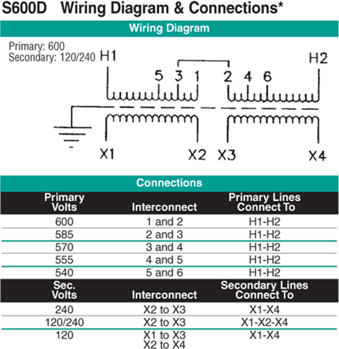
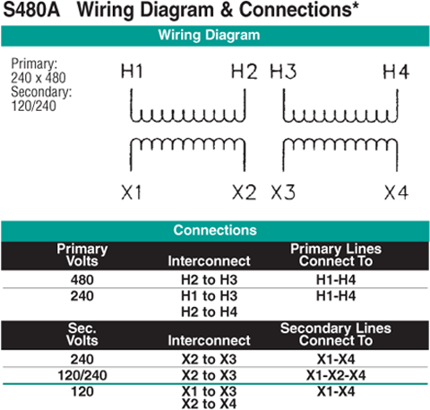
Control transformer wiring diagram. Control Transformer Wiring Diagram Source: www.practicalmachinist.com. Before reading a new schematic, get acquainted and understand all of the I print the schematic plus highlight the signal I'm diagnosing to make sure Im staying on the particular path. Control Transformer Wiring Diagram... I just bought a second doorbell realized the wiring might be trickier than I thought. I have no chimes of any kind. Just hard wiring them for power. Can anyone help me out here? I'd be very grateful. Thanks Electrical Panel Wiring Diagram - Transformer Voltage Drop. The diagram above contains a transformer that takes a 575VAC voltage and translates it into 115VAC. 115VAC is a standard voltage in North America and is utilized for many devices including PLCs, HMIs, switches and more. NOTE: Design figures, wiring diagrams and accessories begin on page 146. Industrial control transformers are designed especially for maintaining a high degree of regulation even at eight times normal load.This results in a larger and generally more expensive transformer.
Batteries Wiring Diagrams. 1 Phase & 3 Phase Wiring. Three Phase Motor Connection Schematic, Power and Control Wiring Installation Diagrams. use transformer input 380,output 220 ACV. Reply. A flyback transformer, sometimes called a line output transformer, is used in older CRT TV's and computer monitors to produce the high voltage required to drive the CRT and electron gun. They also have auxiliary low voltage windings which the TV designers use to power other parts of the TV. Vector Group of Transformer: The three phase transformer windings can be connected several ways. I think in diagrams "SIX WAY TO WIRE STAR WINDING" (Y4 and Y8), (Y10 and Y2) must be Jignesh Parmar has completed M.Tech (Power System Control), B.E(Electrical). He is FIE ,MIE... Abstract: step down transformer 24vac diagram 3 phase heater control factory electrical wiring diagram cyt 431 manual change over switch circuit diagram wiring diagram for level switch 10KW 24V to 0-10v POTENTIOMETER wiring diagram electric Text: TRANSFORMER 9...
...Enclosure Wiring Detail (Shown Open)96 FIGURE 99 - Transformer Wiring Diagram97 FIGURE 100 - UV Control Panel Wiring (8 amps)99 FIGURE Three Phase, 500Va Transformer Wiring Diagram 104 FIGURE 105 - Typical Wiring Diagram for Electric Heat Control Type Vermier 105... A wiring diagram may include the wirings of a vehicle. For example, how the horns are powered and connected to the controller on your steering wheel. Or an electrical wiring diagram can be a 200-page document including all the electrical wirings of an electrical control panel in a huge factory or... The closest I can get to cracking the code for an aftermarket head unit is a $400 dash kit. Has anyone figured out what wires are needed to keep most of the features and succesfully install an aftermarket radio. Its been like 9 years since this model was realeased. I wish i had the time patience and know how to pick it apart. Hey, I'm using a transformer I've never used before on a commercial job. I have 347v lights on a switch but then some pot lights (4" lithonia Retrofit led with driver) which are 120v that need to be controlled by the same switch. So the ol supply house gave me a 347v to 120v transformer but no wiring diagram... I called and they didnt have one (they don't come in boxes). They called the supplier and they couldnt supply a wiring diagram... Weird I know. So it's gets weirder. Two black leads t...

BOJACK EI Type Isolation Transformers PRI.120/208/240 V AC 50/60Hz 24 V AC 40 VA 4031F Class 2 Control Transformers with Foot Mount Replacement for ...
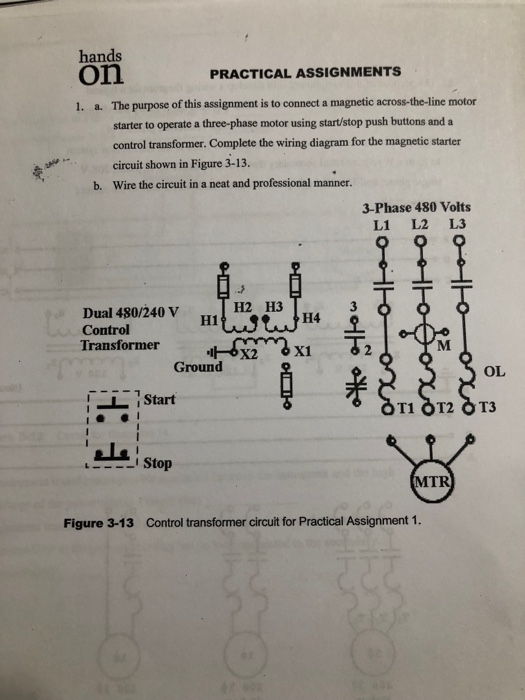
These include ladder diagrams, wiring diagrams, line diagrams, and block diagrams. A "ladder diagram" (considered by some as a form of a Using a transformer allows a lower voltage (120 V AC) for the control circuit while supplying the three-phase motor power circuit with a higher voltage...
Figure 2 - Delta-Delta Transformer Connections (click to expand diagram). The connection diagram on the left shows how a delta-delta connection can be made, either with three single-phase transformers or with one three-phase transformer.
The control transformer needs to be sized (VA rating) based on our known or calculated "load" of devices that will be powered from the transformer in our The wiring diagram is also useful for system startup and later for locating wire routing and devices during troubleshooting. WHITE PAPER.
wire wound around core, including the coil carrying the magnetizing current. The voltage across the entire coil E is simply the volts per turn times the number of turns. FIGURE 2.6 ∆-Y transformer connection and vector diagram. able to circulate around the path formed by the ∆-connected winding.
Typically, control transformers are small (less than 75VA), which places them in a lower cost electrical code Phasor diagrams for QDC, referred to the secondary side of the control transformer. Control wiring Wiring from supervisory or annunciator devices to the terminal blocks may be carried...
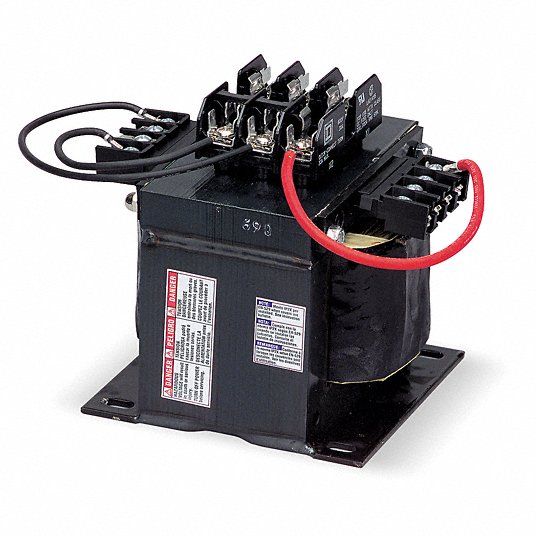
A control transformer as part of a basic power supply circuit, clearly showing the soldered connection terminals for the primary and secondary windings, as well as a firmly grounded metal-to-metal base. Since the failure can come from nearly any metallic object near an energized wire, it seems logical to...
Essentially, motor lighting transformer wiring diagrams illustrate how the voltage across a line can be varied. They can be used for any number of applications where the Lighting transformers are used in various applications, and their wiring diagram can show how the motor transformer actually works.
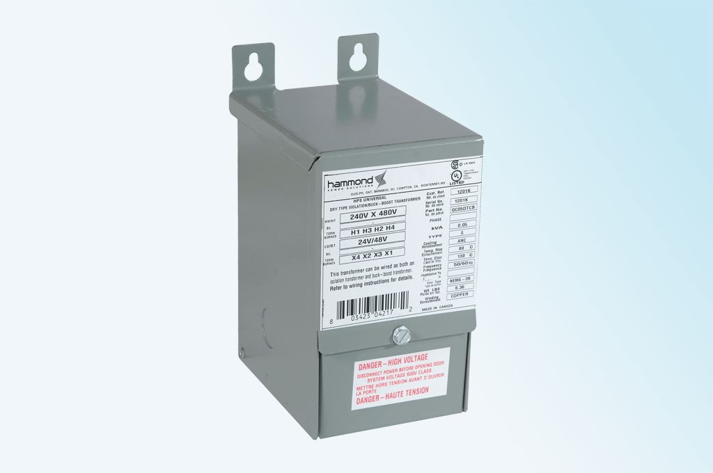
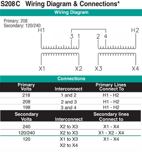
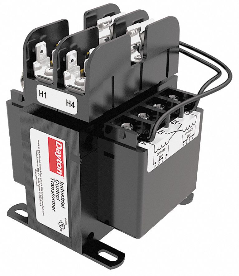
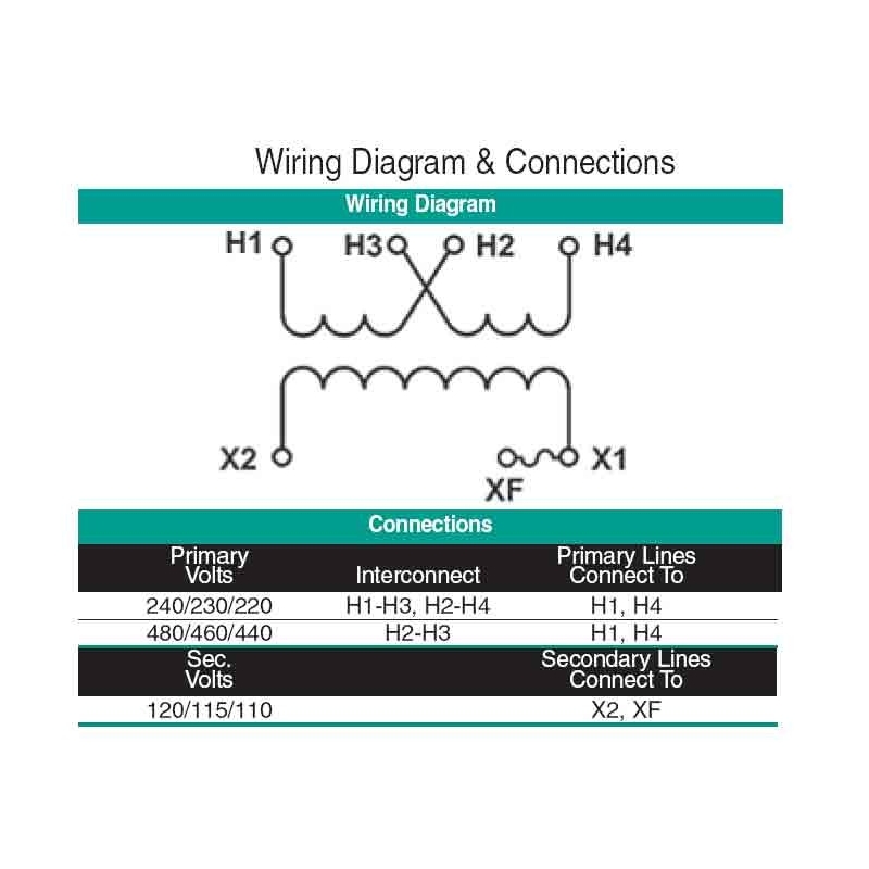
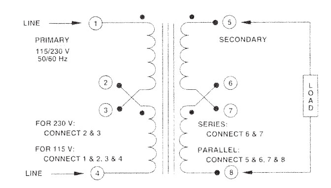
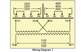
1 HPS Im p e r at o r t m Industrial Control Transformer Wiring Diagrams Literature Code: PHWD- The HPS Im p e r at o r t m series of machine tool industrial molded control transformers are available in many standard offerings.
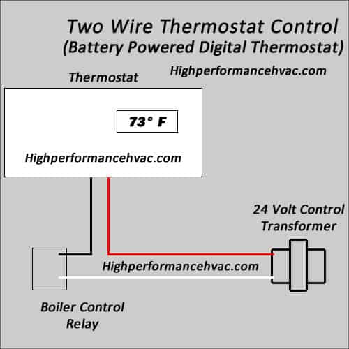
Wiring diagrams help technicians to see how the controls are wired to the system. Many people can read and understand schematics known as label or line diagrams. The components of the diagram will include a transformer, low voltage source, thermostat (switch), humidistat (switch), low voltage...
Wiring diagrams show the conductive connections between electrical apparatus. They show the internal and/or external connections but, in button is enabled via its own auxiliary contact Q11/14-13 and pushbutton 0 (three-wire control contact). Contactor Q11 is de-energized, in the normal course...
Wiring Diagrams for MTA, MTC and AP Transformers. MTE/MTG. MTK. CE Marked Transformers. ቢ See Page 9-10 for Wiring Diagrams. NOTE: For additional information, refer to Cutler-Hammer Industrial Control Transformer Binder B1228A.

Endurance Pro Endurance Pro Control Transformer 40VA, Primary 120, 208, 240V Secondary 24V, HVAC Furnace Multi Tap, Jard 4031F, Packard 42440
Wiring diagrams or connection diagrams include all of the devices in the system and show their physical relation to each other. When a control circuit step-down transformer is used with a standard Bulletin 509 starter, the wiring connection "X" must be removed.
Transformer Basics. Transformers are electrical devices consisting of two or more coils of wire used to transfer electrical energy by means of a changing Its really helpful as it has easy illustration diagrams.Maybe there is need to make the article bold and colorful in terms of wording and some...
Light Switch Wiring. Current Transformer Wiring Diagram Ct Installation With Ammeters For 3 Phase System Electrical On Current Transformer Wiring Diagram - Wiring Diagram - floraoflangkawi.org. diesel generator control panel wiring diagram - Generator Controllers.
Examples of Control Circuits 2- and 3-Wire Control Elementary Diagrams. Low Voltage Release and Low Voltage Protection are the basic control circuits A starter coil with a high VA rating may require a control transform-er of considerable size. A control relay and a transformer with a low VA rating...
Free Download. Circuit Diagram. Car Stereo Wiring. 12V fan on 230V circuit. 12V to 24V DC converter power supply circuit diagram. 24V to 220V 1000W DC AC sine wave inverter for photovoltaic solar system. Power supply without transformer. Step up converter. 220V to 110 V step-down circuit.
[http://www.wrxinfo.com/service\_manuals/](http://www.wrxinfo.com/service_manuals/) Been researching some torque specs for suspension stuff and was surprised about the amount of misinformation and confusion out there across forums and videos. Here ya'll go, hope this helps some of you DIYers.
2 hours ago Industrial Control Transformer Wiring Diagram- wiring diagram is a simplified up to standard pictorial representation of an electrical circuit.It shows the components of the circuit as simplified shapes, and the capacity and signal connections in the company of the devices.








![Industrial Control Transformer Wiring Diagrams - [PDF Document]](https://demo.vdocument.in/img/378x509/reader023/reader/2020112320/586a07de1a28ab847d8ba78c/r-1.jpg)


0 Response to "40 control transformer wiring diagram"
Post a Comment