40 boat tachometer wiring diagram
Nov 03, 2017 · Description: Vdo Gauges Wiring Diagrams And Boat Tach Diagram E Z Go Golf Cart for Boat Gauge Wiring Diagram For Tachometer, image size 1200 X 1362 px, and to view image details please click the image. Here is a picture gallery about Boat Gauge Wiring Diagram For Tachometer complete with the description of the image, please find the image you need. Jun 30, 2020 · Yamaha Outboard Tachometer Wiring | Manual E-Books – Yamaha Outboard Tachometer Wiring Diagram. Wiring Diagram includes numerous in depth illustrations that display the relationship of assorted things. It consists of guidelines and diagrams for different kinds of wiring strategies along with other products like lights, home windows, and so forth.
Even a small boat (3-5 loads) we'd recommend at least 12AWG wire for this. 10AWG for larger boats (5-10 loads) is normal. 8AWG is getting toward over-kill in most cases for boats under 30ft. Remember these are all generalities, there are many valid reasons to make exceptions.

Boat tachometer wiring diagram
Buy A15 Boat Motor Side Mount Remote Control Box with 8 Pin for Mercury Top Mount Single Engine Outboard Motor Control w/Trim 8M newer 8//15/20 four-stroke outboards an adapter harness A01 is required. Matches OEM wiring and cabling as expected, mounting plate with bolts.Single-Engine Controls. 3,983. Jul 9, 2003. #2. Re: wiring diagram for my boat tachometer. Hi Harry,
Click the link below to the Teleflex site and then select the type of engine you have and take a look at the installation guide. Tachs and wire color codes are pretty much standard so the site should do it for you:
Teleflex Support page. View wiring diagrams and schematics for hundreds of popular boats including Lowe, Larson. If you have determined that the Faria Gateway box is defective, there is no direct replacement for Insert PP tach wire in the 2way connector supplied with the new Check for proper locations of gauge's ring terminals according to schematic. IS, A, FB-Sentry ...
Boat tachometer wiring diagram. Engine Instrument Wiring Made Easy. Engine instrument gauges fall into three categories, and there are differences in the terminals and wiring. By Ed Sherman. June 6, 2014. The vast majority of recreational boats in service today are still using analogue instrumentation systems. More modern digital, NMEA-networked, and multifunction gauges may ... I recently re-powered my boat, it had a 1995 Yamaha 2 stroke and I installed a 2008 Yamaha F60TLR 4 stroke. Using the existing wire harness I plugged in everything that had a compatible plug and the motor fired right up. At this point the motor runs, but has no overheat/oil pressure alarms, hour meter or trim indicator. Slip one of the ring connectors on the green wire onto the terminal post on the back of the tachometer marked "GND." Remove one of the screws on the boat's common ground, slip the connector on the other end of the black wire over that screw and thread the screw back into the common ground, tightening the screw with a screwdriver. Boat Tach Wiring Wiring Diagram Dzh8sqfqm1kwqm Yamaha Outboard Wiring Colors Wiring Schematic Diagram 6 Laiser Yamaha Outboard Ignition Switch Wiring Wiring Schematic Diagram Ww 0847 Yamaha Outboard Gauge Wiring Diagram Gm 9776 Yamaha Digital Outboard Tach Wiring Diagram Free Download Tg 3269 Parts Diagram Together With Yamaha 703 Remote ...
Vdo Marine Tachometer Wiring Diagram - Data Wiring Diagram Schematic - Tachometer Wiring Diagram. You are able to always depend on Wiring Diagram as an crucial reference that will help you preserve money and time. With all the aid of the book, you are able to easily do your own personal wiring projects. Dangar Marine; How to install a tachometer in a boat; How to install a tachometer in a boat In this video I install a tachometer in my boat. I wire up the power and then select the number of pulses or cycles my outboard has to get the correct reading. View wiring diagrams and schematics for hundreds of popular boats including Lowe, Larson, Alumacraft, Lund, and others. Files are fully down-loadable and printable pdf format via the Box.net file storage service. The list may take several seconds to populate on the web page. 2 Dec 2015 — The Boating Forum - OMC tach wiring diagram - I want to separate the tach and system check gauges... But since the tach/system check gauge ...
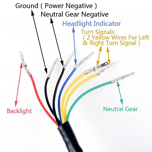
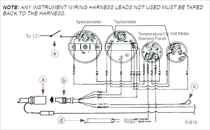
VDO Cylinder Head Temperature Gauge Handlebar/Fairing Mount - 2009. VDO Resitive Gauge wiring Instructions - 2009. Veratron Flex Gauge 52mm NMEA2000 12/24v. ViewLine 52mm Wiring Diagram (2014) ViewLine Standard Resistive Gauges 52mm Installation Sheet (2014) Viewline Temperature Gauges 12/24 Volt (2011) Viewline Temperature Gauges 52mm (2008) Connect the black tachometer wire to the black ground wire. Connect the yellow wire to your lighting wiring. Connect the remaining wire (usually green) from the tach to the wiring for the engine per your boat's wiring scheme. Label each wire with masking tape and a permanent marker. Turn the tachometer over gently so that the backside is exposed. Wiring Diagram For Boat Tachometer - Readingrat throughout Boat Gauge Wiring Diagram For Tachometer by admin Through the thousand photos online regarding Boat Gauge Wiring Diagram For Tachometer, we choices the best selections having best image resolution exclusively for you, and now this images is actually considered one of images choices inside our best images gallery in relation to Boat ... female blade terminal.6. Connect a wire to the tach stud marked "SIG" (signal) and secure with a nut and lockwasher. Connect the opposite end to a terminal or wire originating from the unrectified side of the alternator. On most late model outboards, a tach hook-up wire can be found at the control box. Tach plug-in harnesses are

Wiring Diagram For A 1972 Glastron Model 177 0 Boat
Connect wires to tachometer per instructions. Secure the tachometer using the bracket, nuts and lockwashers provided. 1. 2. 3.2 pages

70 Hp Johnson 1988 Wiring To Tachometer Etc Diagram
Use a wiring kit to connect the tachometer to the plug-in connector on the remote control or accessory electrical cable. Use Plug-In Connector Kit P/N 0174732 when installing tachometer only. Use Plug-In/Fuse Block Kit P/N 0173611 when installing tachometer with other accessories.

Faria Tach Wiring | schematic and wiring diagram
Vdo Marine Tachometer Wiring Diagram - Data Wiring Diagram Schematic - Tachometer Wiring Diagram Wiring Diagram contains several detailed illustrations that present the relationship of varied things. It consists of guidelines and diagrams for various types of wiring techniques as well as other items like lights, home windows, etc.

Tachometer Color Code Yamaha F40La Outboard - DIAGRAM 115 ...
See Diagram F. III. Calibrating the Tachometer a second piece of wire (long enough to reach the light switch) into another spade connector. Attach this con-nector to a terminal on the remaining lamp socket, which will be referred to as Socket B. 9. Reconnect the battery and turn on the ignition to make sure the tachometer is working. When you ...
Universal Motorcycle Dual Odometer Speedometer Gauge ...
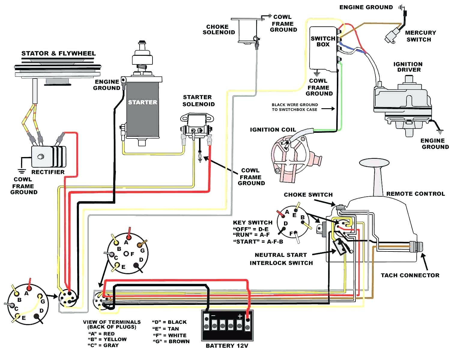
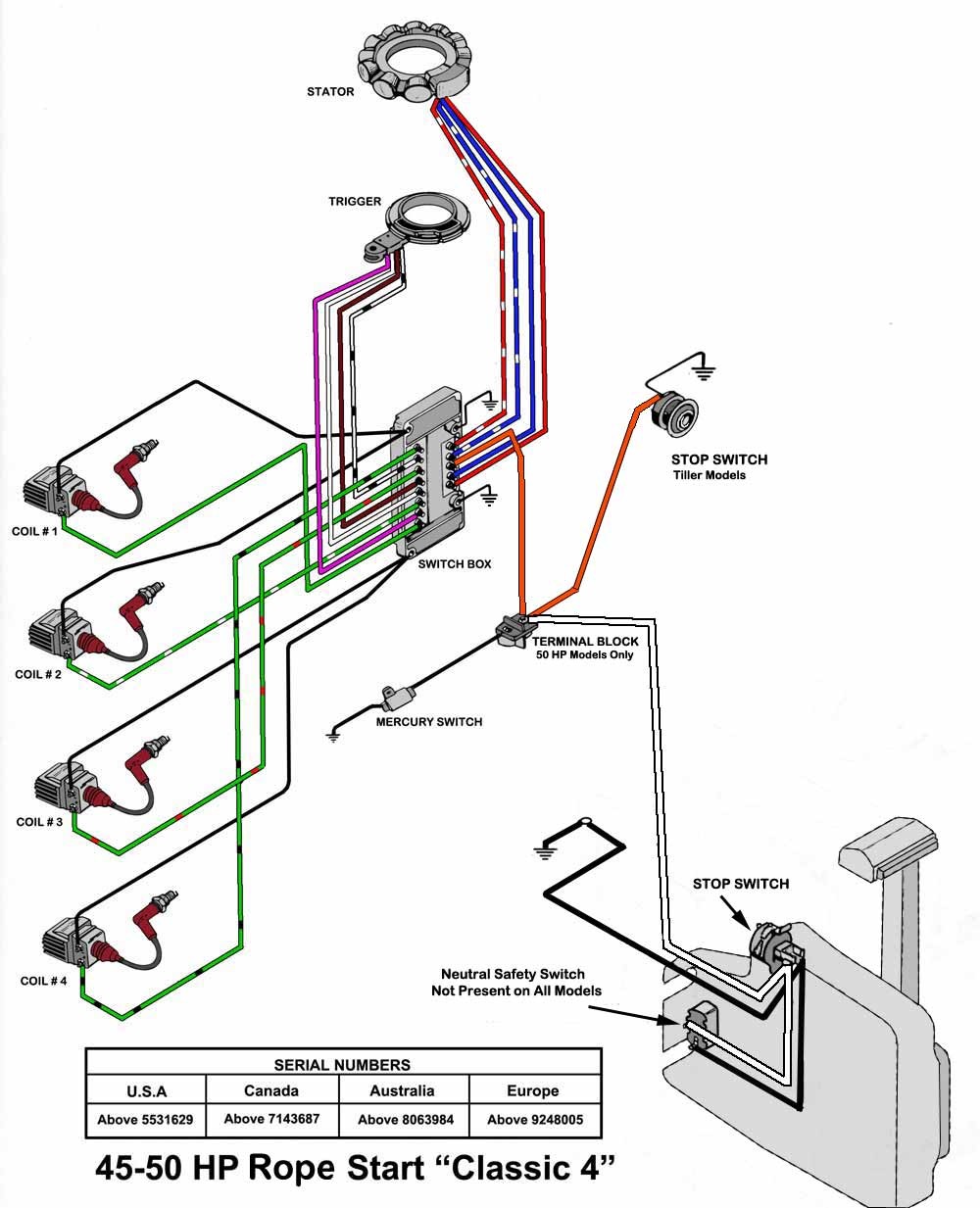
Omc tachometer wiring diagram. It shows the elements of the circuit as simplified forms, and also the power and signal links in between the devices. Technical Information within 70 Boats with tachometers allow the boat owner to govern and moderate the engine's rpm rate during wide-open throttle operation.

Docking
Feb 7, 2019 - Where To Hook Tach To On Ignition Key Switch On An Omc Evinrude For Wiring Diagram For Boat Ignition Switch In Tachometer Wiring Diagram, ...

2014 Yamaha 150 Hp Trim Wiring Diagram : Yamaha 225 4 ...
Standard Case - Wire diagram. 8. Reconnect the battery. Reconnect Power. Continued on next page. Fine Adjustment Pot. Magnetic Pick-Up Tachometer. The Faria Marine Instrument Bracket Mount Dual Engine. Synchronizer is designed to Like a tachometer, the Synchronizer counts "pulses" from the ignition or tach tachometer and synchronizer wiring ...

115 Hp Yamaha Outboard Tach Wiring Diagram
Rpm Digital Tachometer Gauge 52mm Small Not Marine Teleflex Vdo Wrx Sti Omori For In Wexford Town From Mechauto. Tachometer wiring excerpt of 123GT diagram 1800 tach wiring is substantially the same. This is the circuit diagram of Digital Tachometer Digital RPM Meter which can be used for cars or motorcycles with 2 and 4 stroke petrol engines ...

Boat Gauge Wiring Diagram For Tachometer | Fuse Box And ...
Yamaha Multifunction Fuel Management Gauge Wiring The Hull Truth Boating And Fishing Forum. Wiring Diagram For Yamaha Command Link Tachometer Kit Decks. Yamaha Multifunction Gauge Kit Installation. 6y5 8350t D0 00 Tachometer Install Yamaha Outboard Parts Forum. Any Yamaha Gauge Wiring Magicians The Hull Truth Boating And Fishing Forum.

End of the journey
Faria Beede Instruments, Inc. 75 Frontage Road, Suite 106. North Stonington, CT 06359, USA . Telephone: 860.848.9271 Toll Free Technical Support: 800.473.2742 Sales ...
![[DIAGRAM] Mercury Outboard Tachometer Wiring Diagram FULL ...](https://i2.wp.com/stickerdeals.net/wp-content/uploads/2017/10/yamaha-wiring-diagram-tachometer-the-wiring-diagram-readingrat-for-boat-gauge-wiring-diagram-for-tachometer.jpg)
[DIAGRAM] Mercury Outboard Tachometer Wiring Diagram FULL ...
This will neither damage a Faria® tachometer ... marine use. It is recommended that insulated wire ... Consult your engine manual for its.2 pages

115 Hp Yamaha Outboard Tach Wiring Diagram
**Full Parts List Below:***Amazon Electric Section: https://www.amazon.com/shop/TBNation?listId=321RPSYSZZZN3&ref=inf_list_own_tbnation_cp***Switch Panels, A...

Farium Outboard Tachometer Wiring Diagram - Wiring Diagram ...
Sep 14, 2021 · The boat s bilge pump float switch. Vdo gauges wiring diagrams and boat tach diagram e z go golf cart for boat gauge wiring diagram for tachometer image size 1200 x 1362 px and to view image details please click the image. Attach this con nector to a terminal on the remaining lamp socket which will be referred to as socket b.

Teleflex Tach Wiring | schematic and wiring diagram
Yamaha Multifunction Gauge Kit Installation. 6y8 yamaha gauges diagram the hull to simrad 6yc multifunction meter 2018 outboard command link plus wiring fm gauge manualzz tachometer kit installation round digital sd gps wires 2819u 00 owner s manual boat pdf any magicians main bus harness tach install marine network single engine f75b f80b f90b f100d motor and hour images 07 f50 efi what ...
Yamaha 6y8 Multifunction Meter Wiring Diagram - Wiring Diagram
Smart Actuator II™ Control System Wiring Diagram - Remote Enable Switch . such as Volvo Diesel or any gasoline engine, a mechanical tachometer. The Faria Marine Instrument Bracket Mount Dual Engine. Synchronizer is case of outboard engines). Like a tachometer, the Synchronizer counts "pulses" from. The two most critical parts of the EEC ...

Yamaha Outboard Tach Wiring Diagram - 12
View wiring diagrams and schematics for hundreds of popular boats including Lowe, Larson. If you have determined that the Faria Gateway box is defective, there is no direct replacement for Insert PP tach wire in the 2way connector supplied with the new Check for proper locations of gauge's ring terminals according to schematic. IS, A, FB-Sentry ...
Omc Schematic Diagram - Wiring Diagram
3,983. Jul 9, 2003. #2. Re: wiring diagram for my boat tachometer. Hi Harry,
Click the link below to the Teleflex site and then select the type of engine you have and take a look at the installation guide. Tachs and wire color codes are pretty much standard so the site should do it for you:
Teleflex Support page.

29 Yamaha Outboard Tachometer Wiring Diagram - Wiring ...
Buy A15 Boat Motor Side Mount Remote Control Box with 8 Pin for Mercury Top Mount Single Engine Outboard Motor Control w/Trim 8M newer 8//15/20 four-stroke outboards an adapter harness A01 is required. Matches OEM wiring and cabling as expected, mounting plate with bolts.Single-Engine Controls.
Boat Tachometer Wiring Diagram Collection

Trouble with gauges wiring Page: 1 - iboats Boating Forums ...
28 Suzuki Outboard Tachometer Wiring Diagram - Wire ...
Help, wiring gauges - The Hull Truth - Boating and Fishing ...
Yamaha Outboard Tachometer Wiring Diagram - Cadician's Blog

28 Suzuki Outboard Tachometer Wiring Diagram - Wire ...

Suzuki Outboard Tachometer Wiring Diagram Pictures ...

Took a trip around the islands around Sai Kung. Happened to pass the fisherman along the way. Loved the landscape behind him.

Yamaha Outboard Tachometer Wiring Diagram | Free Wiring ...

Faria Tachometer Wiring Diagram

Suzuki Outboard Tachometer Wiring Diagram | Free Wiring ...
Converting Yamaha 2-Str To Analog Gauges? - Page 2 ...
WTB used Yamaha tach for 01 250 OX66 - The Hull Truth ...
Farium Outboard Tachometer Wiring Diagram - Wiring Diagram ...
Yamaha tach problem - The Hull Truth - Boating and Fishing ...
Boat Tachometer Wiring Diagram - MORPHINE-AND-DRUGS

I have an 88 Sea Ray, I need a wiring diagram for the ...

Boat Gauge Wiring Diagram For Tachometer | Fuse Box And ...

Faria Multifunction Wiring Doagram To 2018 Df60 Suzuki ...
![[HZ_8371] Peterbilt Tachometer Wiring Diagram Download Diagram](https://static-assets.imageservice.cloud/4257152/stewart-warner-tach-wiring-diagram-wiring-diagram.jpg)
[HZ_8371] Peterbilt Tachometer Wiring Diagram Download Diagram
Faria Tachometer Wiring Diagram
![[EH_0694] 1985 85 Hp Johnson Outboard Motor Wiring Diagram ...](https://static-assets.imageservice.cloud/2817095/mariner-25-hp-wiring-diagram-wiring-diagrams-schema.jpg)
[EH_0694] 1985 85 Hp Johnson Outboard Motor Wiring Diagram ...
0 Response to "40 boat tachometer wiring diagram"
Post a Comment