39 plate heat exchanger piping diagram
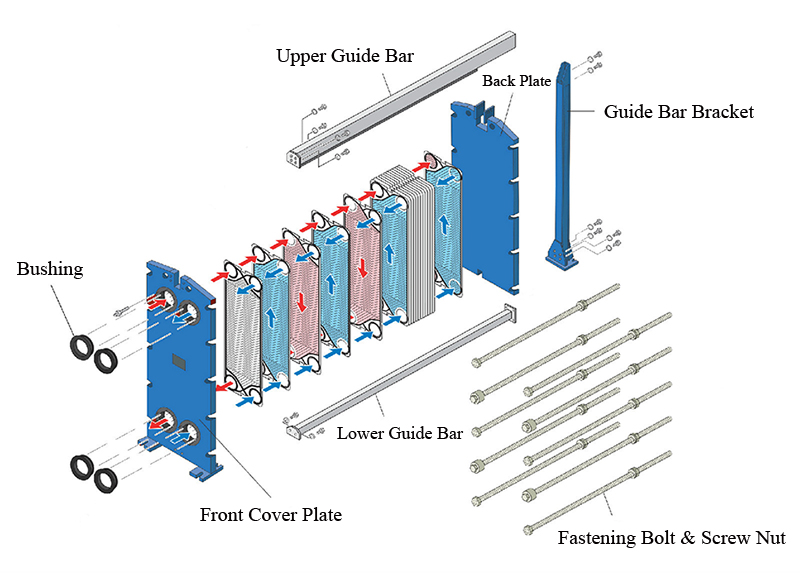
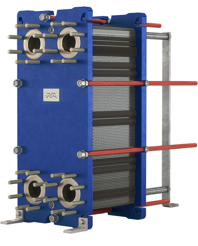
"GPX" heat exchangers are of a gasketed plate pack design. Some features and benefits of this design are its small size, light weight and high efficiency in transferring heat with either large or small fluid temperature differences. Design produces high turbulence resulting in high heat transfer coefficients, full counterflow of hot and cold fluids, andRead more THE MAIN COMPONENTS OF THE PLATE HEAT EXCHANGER AND THEIR FUNCTIONS. In ALFA LAVAL Plate Heat Exchangers, heat is transferred from one medium to another through thin metal plates which have been pressed into a special pattern. 3. CONNECTIONS Holes matching the piping lead through the frame plate, permitting 1.
Piping at spiral and plate exchangers is also positioned to allow the opening of covers and the removal of plates. Control at the spiral exchanger are located on the ends of the unit, clear of the cover plate swing area , and at the front and on one side for the plate exchanger. Piping is elevated similar to shell & tube exchanger.

Plate heat exchanger piping diagram
Plates are pressed in materials between 0.5 and 1.2 mm thick and plates are available with effective heat transfer area from 0.03 to 3.5 m 2. Up to 700 plates can be contained within the frame of the largest Paraflow exchanger, providing over 2400 m 2 of surface area. Flow ports and associated pipework are sized in proportion to the plate area ... Created Date: 12/20/2012 10:29:06 AM heat exchanger functions as the condenser, and the "Source" heat exchanger functions as the evaporator. In fi gure 1-4, the reversible water-to-water heat pump now provides chilled water on the load side instead of hot water. The load heat exchanger becomes the evaporator, and the source heat exchanger becomes the condenser.
Plate heat exchanger piping diagram. Quite often, the heat exchanger is insulated to minimize this effect. Nevertheless, any heat radiating from the heat exchanger is thermal energy that could have gone to your floors. In addition, antifreeze as a heat transfer medium is inferior to plain water. Overall, a heat exchanger system is 10 to 20% less efficient than an open system. correct configurations, see diagram at top of page 4.) A lift or back pressure in the steam trap return piping can flood the heat exchanger shell and cause severe water hammer as steam enters the flooded shell. The resulting water hammer can damage the steam trap, the steam regulating valve, the heat exchanger tubes and cause The plate heat exchanger is installed between the chillers and the towers to stop the condenser water from running back to the towers, and flooding them, losing all the water from the system. If used they will bring some complications, such as: Pipework cleaning and flushing; Water Balancing; Sequence of Operations / Controls; Below is a simple ... A plate heat exchanger is a type of heat exchanger that uses metal plates to transfer heat between two fluids.This has a major advantage over a conventional heat exchanger in that the fluids are exposed to a much larger surface area because the fluids are spread out over the plates. This facilitates the transfer of heat, and greatly increases the speed of the temperature change.
Piping arrangement diagram for SEC series heat exchangers. Figure P.1 Liquid Flow Heat Transfer Diagram The liquid-to-liquid heat exchanger uses a heat transfer plate to transfer heat from one liquid to another. This method requires a stable water supply from the user. Figure P.2 Drive and Heat Exchanger Plumbing Arrangement Title Publication Apart from the internal structure, another important diagram for heat exchanger design, is the piping & instrumentation diagram or P&ID for heat exchanger. Following diagram is a typical P&ID arrangement for a shell & tube heat exchanger. This post explains the guidelines for creating a detailed P&ID diagram for a shell and tube exchanger. Manuals for the HISAKA Plate Heat Exchanger consist of the following seven related documents. 1. Installation Manual, 2. ... 8 Piping P9~ 9 Storage/Preservation P13 10 Inquiries P13 . P1 : ... Assembly Drawing and Wiring Diagram. If inexperienced worker performs piping / wiring work unloading, there is ...
5 T temperature [ K ] U overall heat transfer coefficient [ W / m2K ] v specific volume [ m3 / kg ] w flow velocity [ m / s ] Greek α thermal diffusivity,α = k / ρc p [m2 / s ] β heat transfer area per volume [m2 / m3] δ gap between the plates of a plate or spiral heat exchanger [ m ] ε heat exchanger effectiveness [ - ] 8 Additional Plate Heat Exchanger Benefits ØNo stored water to harbour bacteria ØFast heat up -almost instant -from cold ØLow water content, less water to treat ØLow water content, smaller expansion vessels ØHigh pressure rating for sealed systems ØCan be expanded to increase performance ØHigh temperature drop on primary, small flow rates, ... The heat exchanger in this application isolates the glycol loop from the boiler water. To select a heat exchanger for a snow melt application: a. Determine the Total BTUh required ( using guidance from your radiant tube supplier) for the snow melt system. b. Select the appropriate heat exchanger from the table, based on the total BTUh required. Hi. From the uk just installed an American made shaver furnace and plumbed in according to your video on YouTube (very very helpful thanks). So I'v got a 25plate heat exchanger 0.69m2 surface.. it's all working and the boiler side is extremely hot but the heat exchanger is not transferring the heat into the house side of things enough to stop the boiler coming on.
Wood Boiler Plumbing | Twinsprings Research Institute
4-Valves V-4 and V-5 are used in conjunction with the by-pass piping to isolate the heat exchanger when the wood fuel boiler is not in operation for extended periods of time. 5-Circulator pumps must be sized correctly to provide; sufficient flow to meet the building load and to over-come head resistance of the piping, fittings, valves and ...

Schematic of plate heat exchanger. | Download Scientific ...
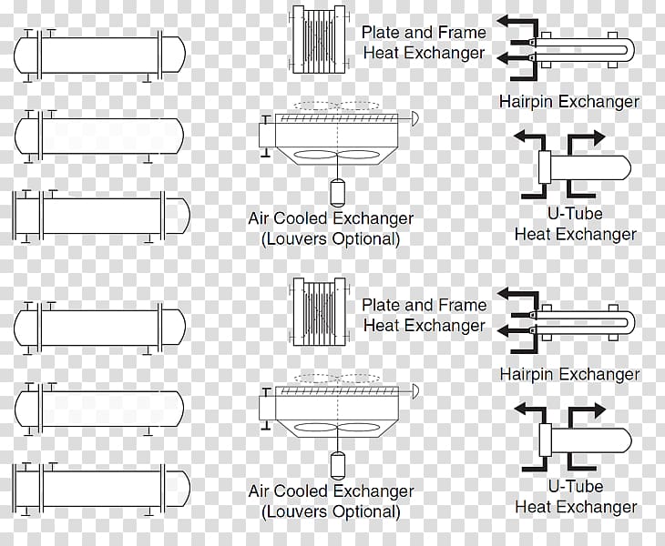
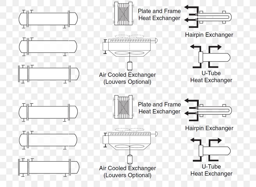
Some heat exchanger advertises the availability of finned tubes in a hairpin or double pipe heat exchanger. These would always be longitudinal fins, rather than the more common radial fins used in a cross-flow finned tube heat exchanger. In a double pipe heat exchanger design, an important factor is the type of flow pattern in the heat exchanger.
Water to Air Brazed Plate Heat Exchanger, 50/60 Plate ...
Piping a plate heat exchanger for heating domestic water The plate heat exchanger will normally be the first component in the primary loop after the pump. It is important to mount the heat exchanger so the longest side is vertical to allow the air to escape without trouble.

Heat Exchanger Guide Part 2: How to Connect an Air Heat ...
Plate and Frame Heat Exchangers. In the PHE the plates create a frame where the plates are pressed with headers and tie bars, and the seal is guaranteed by gaskets.Gaskets, in addition to their sealing effect, serve to direct the flow of the fluids, and are placed along the grooves at the edges of the plates. The maximum temperatures used for sealing heat exchangers are between 80°C and 200 ...

Plate Heat Exchanger Equals Higher Energy Efficiency - The ...
Plate and Frame Heat Exchanger Piping Diagram. Primary/Secondary Chilled Water Instrumentation Diagram. Radial Roof Exhaust Fan Detail. Rectangular Transitions, Offsets, and Elbows. Refrigerant Piping Detail. Relief and Intake Gooseneck Detail. Restraining Method for Mechanical Joint Valve.
Piping and instrumentation diagram Plate heat exchanger ...
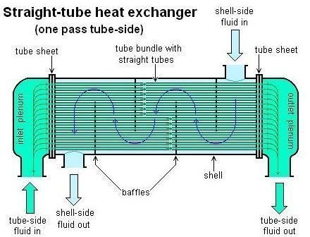
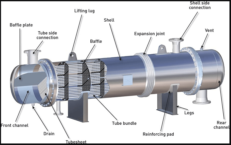
Fig.1 :Diagram showing construction of a typical Shell and Tube Heat Exchanger These heat exchangers are generally designed, fabricated, inspected and tested as per API 660 / EN-ISO 16812 / TEMA. The DEP for the design & construction of the shell & tube heat exchanger is DEP 31.21.01.30 - Gen.

Number of heat exchanger plates as a function of the ...
In ALFA LAVAL Plate Heat Exchangers, heat is transferred from one medium to another through thin metal plates which have been pressed into a special pattern. 3. CONNECTIONS Holes matching the piping lead through the frame plate, permitting the media to enter into the heat exchanger.Threaded studs around the holes secure the pipes to the equipment.
35 Plate Heat Exchanger Diagram - Wiring Diagram Database
Product Drawings. Piping Diagram. Technical Papers. 3D-Drawings. Spec Sheets. CEMLINE® has made a series of typical piping arrangements for the Model Series: SEH, SSH, SWH, and USG. These drawings are in .DWG format or Adobe®Acrobat® (PDF) format. The Acrobat Reader is available free from Adobe. Note: Select the model and click on the ...

Proper Heat Exchanger Piping | ControlTrends
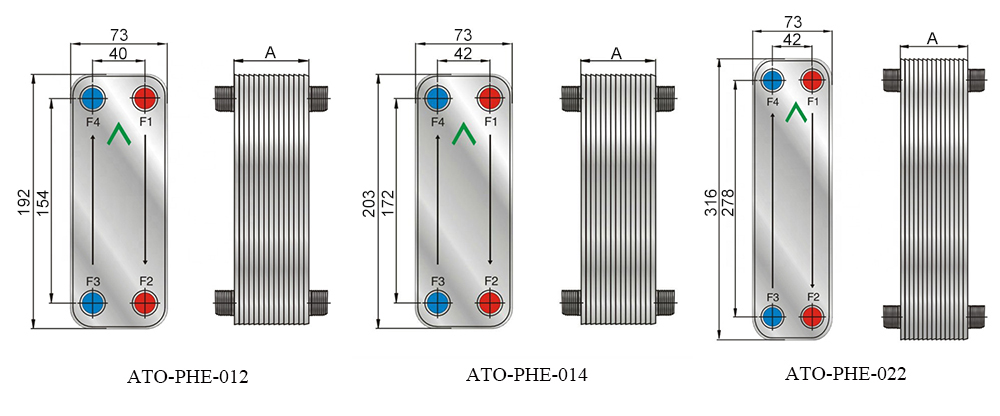
The front plate of SWEP BPHEs is marked with an arrow, either on an adhesive sticker or embossed in the cover plate. This marker indicates the front of the BPHE and the location of the inner and outer circuits/channels. With the arrow pointing up, the left-hand side (ports F1, F3) is the inner circuit (for asymmetric
The Shell and Tube Heat Exchanger as One of Several Types ...
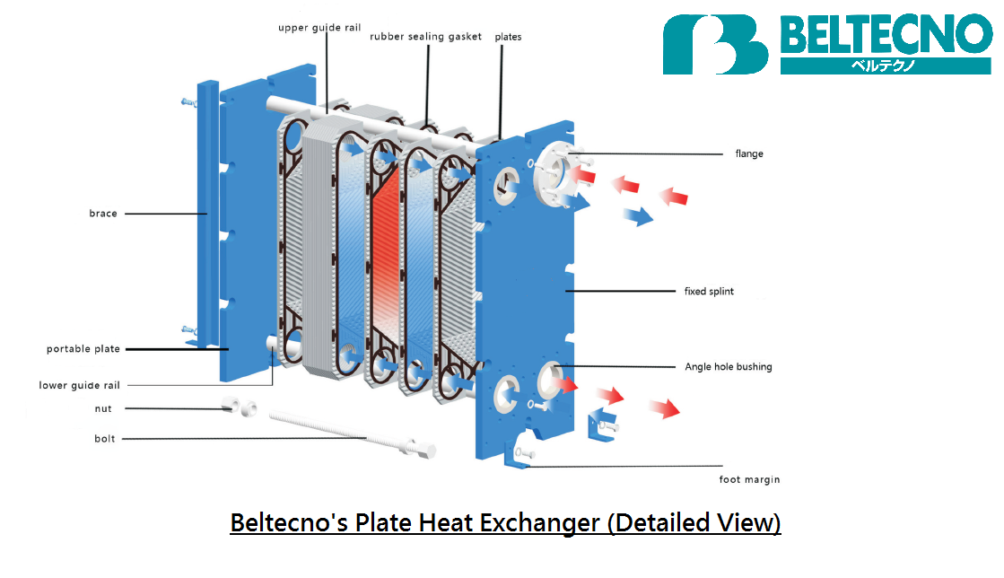
-The heat exchanger must be set so that pipe connections can be made without the use of excessive force. However, ... Figure 4 - Plate Heat Exchanger Part Diagram Figure 3 shows the CCT 4.0 Installed on heat exchanger testing for internal defects. Figure 4 shows the typical
Chemical reactors
• Connect a pipe in the way it is meant to be connected to the plate heat exchanger. Gasket and lining can be damaged if a pipe is connected in the wrong way. • On semi-welded units it is a safety issue if the wrong pipe is connected to the wrong port, double check that the correct media is connected to the correct port according to the PHE ...

Design Resources: Choosing The Right System Type - Solar ...
• Connect a pipe in the way it is meant to be connected to the plate heat exchanger. Gasket and lining can be damaged if a pipe is connected in the wrong way. • On semi-welded units it is a safety issue if the wrong pipe is connected to the wrong port, double check that the correct media is connected to the correct port according to the PHE ...
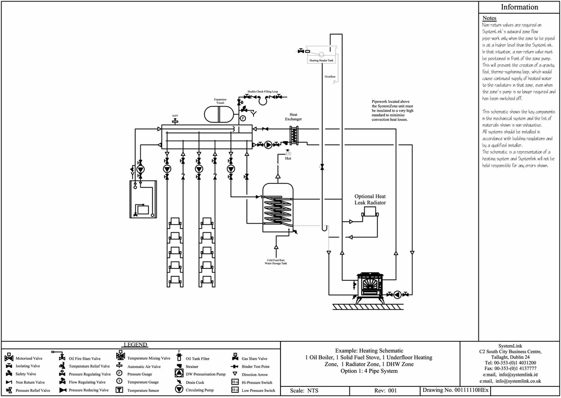
Plate Heat Exchangers
Plate and frame heat exchangers are made of corrugated plates on a frame. This design creates high turbulence and high wall shear stress, both of which lead to a high heat transfer coefficient and a high fouling resistance. F luids travel within the heat exchanger. The two streams flow counter currently.
Schematics of the heat exchanger -(a) Crossflow plate heat ...
Plate Heat Exchanger Piping. Piping is positioned to allow the opening of covers and removal of plates. Controls are located at the front and on one side for the plate exchangers. Piping is elevated similar to that for shell and tube heat exchangers.
Piping And Instrumentation Diagram Plate Heat Exchanger ...
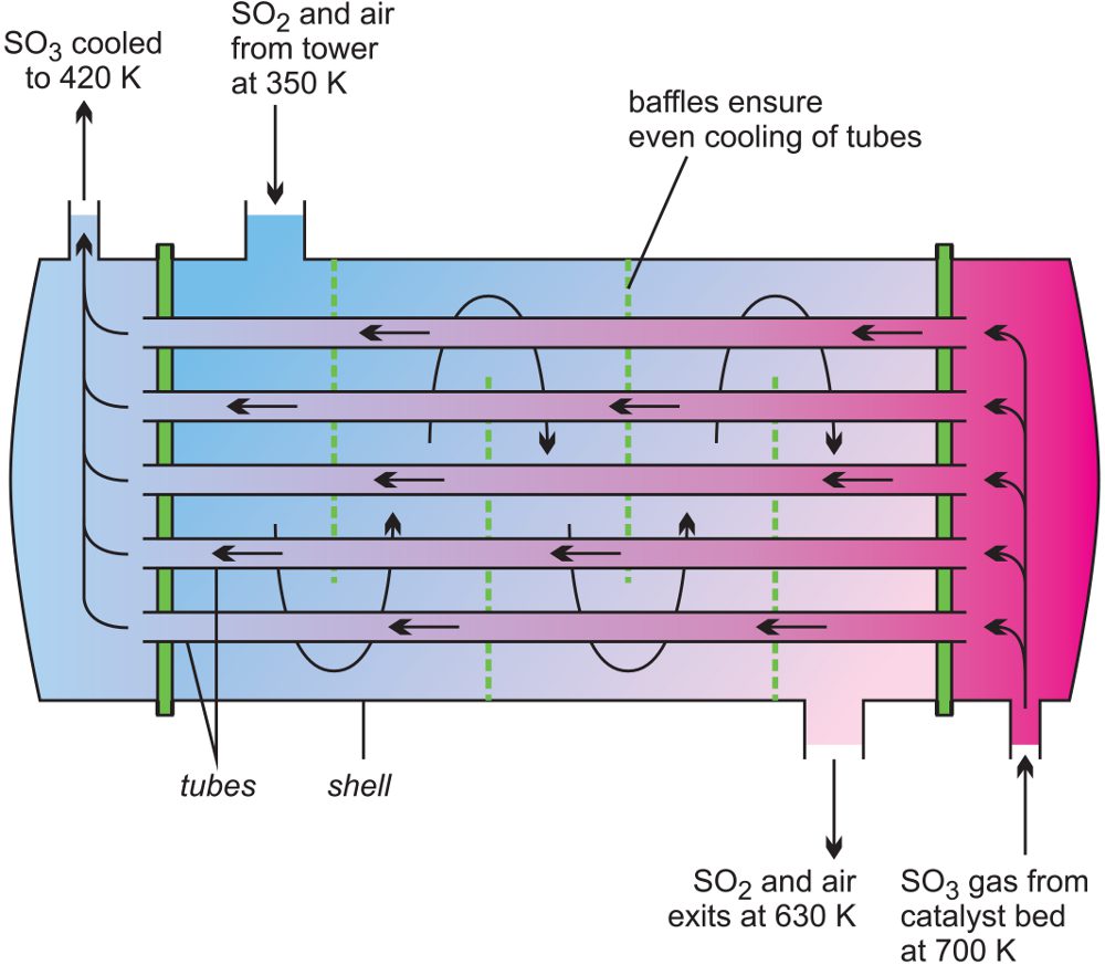
Plate. Figure 1 Tube and Shell Heat Exchanger. A plate type heat exchanger, as illustrated in Figure 2, consists of plates instead of tubes to separate the hot and cold fluids. The hot and cold fluids alternate between each of the plates. Baffles direct the flow of fluid between plates. Because each of the plates has

Diagram of a typical Plate Heat Exchanger | mcd plate heat ...
Connections. Holes matching the piping lead through the frame plate, permitting the media to enter into the heat exchanger. For smaller connection sizes, ...

Apa itu Plate Heat Exchanger (PHE) ? - Prima Handal
3.3 Piping Piping to the plate heat exchanger shall be designed so that it’s thermal expansion and weight do not put too much force on the nozzles causing premature failure. Any forces or moments applied to the nozzles of the plate heat exchanger must be ap-proved by Armstrong.
Gasketed Plate and Frame Heat Exchangers - Gasketed Plate ...
heat exchanger functions as the condenser, and the "Source" heat exchanger functions as the evaporator. In fi gure 1-4, the reversible water-to-water heat pump now provides chilled water on the load side instead of hot water. The load heat exchanger becomes the evaporator, and the source heat exchanger becomes the condenser.

Experimental Schematic Diagram Note: Main Equipment: 1 ...
Created Date: 12/20/2012 10:29:06 AM

3D-schematic view of (a) fin plate heat exchangers and (b ...
Plates are pressed in materials between 0.5 and 1.2 mm thick and plates are available with effective heat transfer area from 0.03 to 3.5 m 2. Up to 700 plates can be contained within the frame of the largest Paraflow exchanger, providing over 2400 m 2 of surface area. Flow ports and associated pipework are sized in proportion to the plate area ...
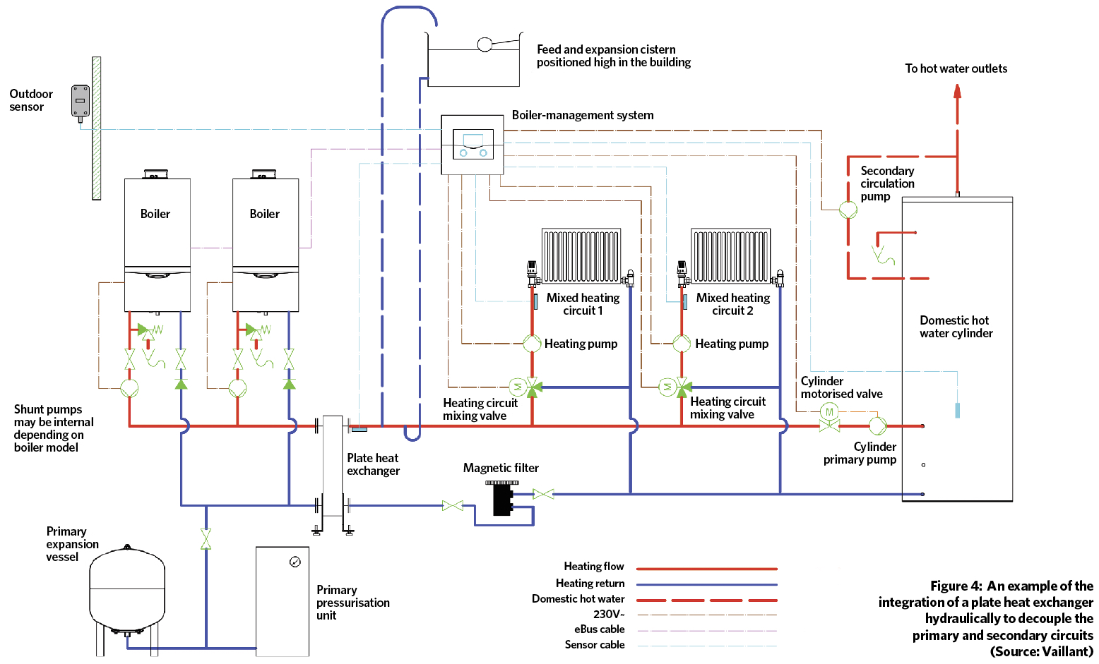
Module 108: Applying plate heat exchangers to integrate ...
Schematic diagram of the measurement stand : 1-Plate heat ...

Plate Heat Exchanger, How it works - working principle ...
How does a plate heat exchanger work? - Quora

CHEMICAL ENGINEERING: PLATE HEAT EXCHANGERS
![Schematic of a plate heat exchanger [47]. | Download ...](https://www.researchgate.net/profile/H_Jouhara/publication/324811679/figure/fig8/AS:630480231751687@1527329609086/Schematic-of-a-plate-heat-exchanger-47.png)
Schematic of a plate heat exchanger [47]. | Download ...

BN-DG-C01E Plant Layout - Exchangers
How does a plate heat exchanger work? - Quora

Gasketed Plate & Embossed Plate

Wiring Diagram: 29 Steam To Hot Water Heat Exchanger ...
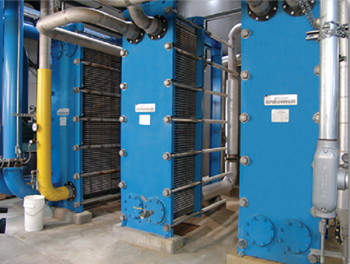
Plate Heat Exchanger Installation Method Statement

China Welded Plate Heat Exchanger Suppliers and ...

Figure 5. Basic structure of plate heat exchanger (PHE ...

Heat Transfer Package

Representative schematic view of the plate heat exchanger ...
Types of Heat Exchanger- according to construction - The ...
Water to Air Brazed Plate Heat Exchanger, 50/60 Plate ...

Meat skewers on a tray

Seafood Lunch
0 Response to "39 plate heat exchanger piping diagram"
Post a Comment