42 draw the shear diagram for the beam. 7.93
Feb 29, 2020 · Solved 7 93 Draw The Shear Diagram For Beam 1 Transtutors. Cantilever Beam Shear Moment Diagram. A Cantilever Beam Ab Supports Couple And Concentrated Load As Shown In The Figure Draw Shear Force Bending Moment Diagrams For This Bartleby. Solved Draw The Shear Diagram For Cantilevered Beam Chegg. Draw Your Shear Force And Bending Moment ... Problem 7.93. Draw the shear diagram for the beam. Click on add discontinuity to add discontinuity lines. Show transcribed image text ...
7.93 Draw the shear diagram for the beam. Jan 11 2021 10:54 PM. 1 Approved Answer. Amol A answered on January 13, 2021. 5 Ratings, (18 Votes). Maxm SF =.1 answer · Top answer: Maxm SF = 3.75 kip at centre.
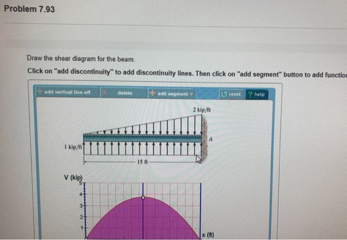
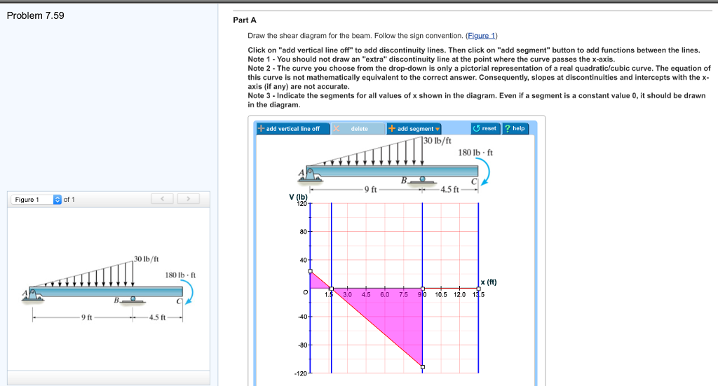
Draw the shear diagram for the beam. 7.93
7–22 Determine the internal normal force, shear force, and moment at points D and E in the overhang beam. Point D is located just to the left of the roller support at B, where the couple moment acts. Exercises Corresponding to Section 7.2 7–46 Draw the shear and moment diagrams for the beam (a) in terms The horizontal beams under this bridge surface will be supporting load forces perpendicular to the length of the beam. To analyze the internal shearing forces and moments in these beams we could use shear and moment diagrams. Image by Alethe CC-BY-SA 3.0. To create the shear force diagram, we will use the following process. Solve for all ... For the beam and loading shown, (a) draw the shear and bending-moment diagrams, (b) determine the maximum absolute values of the shear and bending moment.
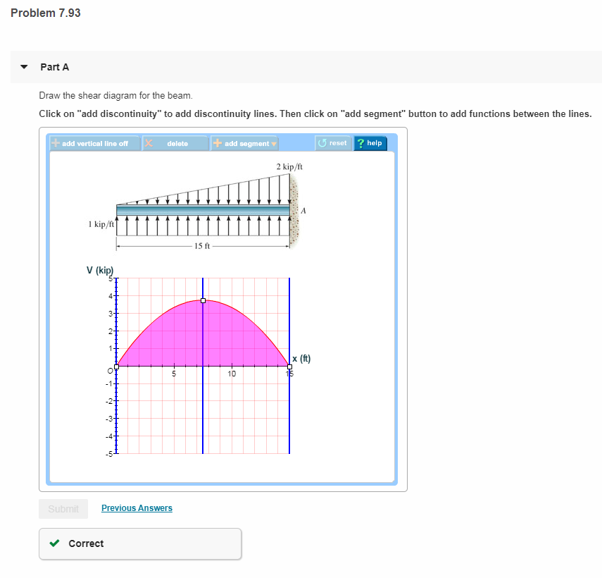
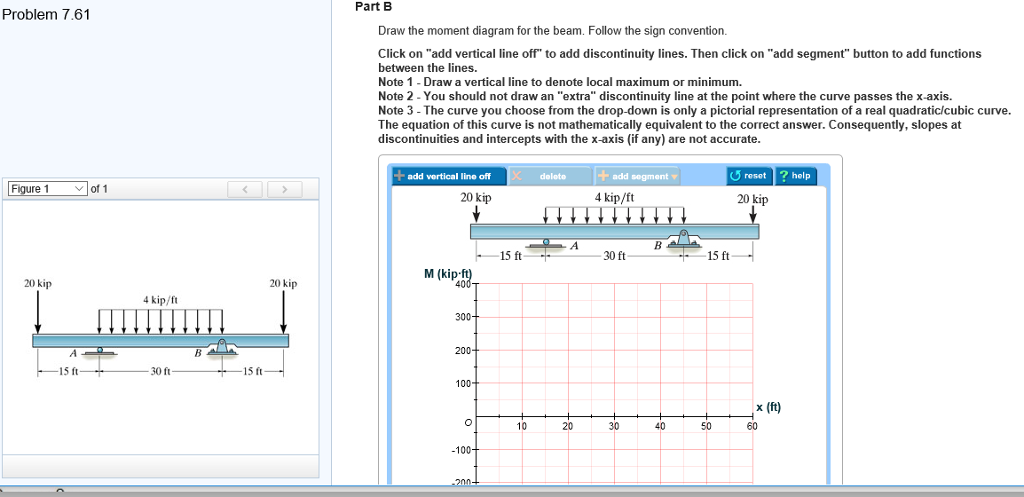
Draw the shear diagram for the beam. 7.93. See the answer See the answer done loading. 7.93 Draw the shear diagram for the beam. Expert Answer. Who are the experts? Experts are tested by Chegg as specialists in their subject area. We review their content and use your feedback to keep the quality high. 100% (9 ratings) Transcribed image text: Problem 7.93 Draw the shear diagram for the beam Click on add discontinuity to add discontinuity lines. Then click on "add segment" ... While drawing shear force diagram (SFD), when we start from right end of the beam, upward forces are considered negative and downward forces are considered positive as given above. Transcribed image text: Problem 7.93 〈 3016 〉| Draw the shear diagram for the beam. Follow the sign convention. (Figure 1) Click on "add vertical line ...
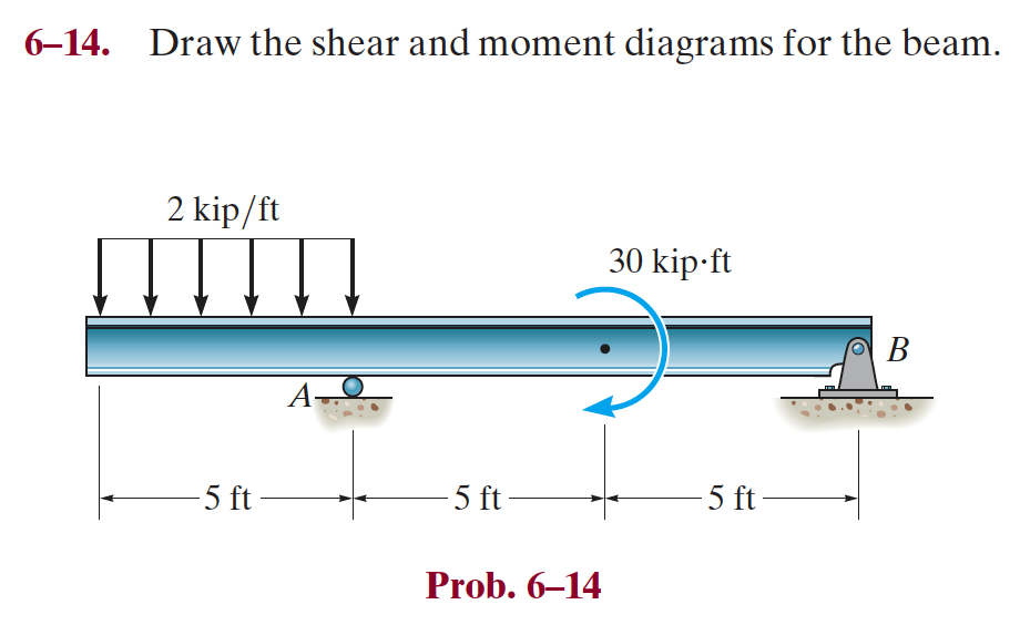
In many instances multi-span beams are used in design, and consequently it ... sketch the shear force and bending moment diagram. ... 1793 kN ---- 7.93 kN. Draw the moment diagram for the beam. Draw the moment diagram for the beam. This problem has been solved! See the answer ... Solution for 2 kip /ft 1 kip/ft -15 ft - Prob. 7-93. Q: The procedure of designing spread footing foundations on the basis of field exploration data (standa... A: The footing takes all the load coming from slab beam and column thus being the most important elemen... Answer: As long as you are consistent it does not really matter which you consider positive and which you consider negative. To fall in line with general practice I recommend you consider sagging moment as positive and hogging moment as negative.
Problem 7.86 < 10 of 10 A Review Part B Draw the moment diagram for the beam. Follow the sign convention. Click on "add vertical line off" to add discontinuity ... For the beam and loading shown, (a) draw the shear and bending-moment diagrams, (b) determine the maximum absolute values of the shear and bending moment. The horizontal beams under this bridge surface will be supporting load forces perpendicular to the length of the beam. To analyze the internal shearing forces and moments in these beams we could use shear and moment diagrams. Image by Alethe CC-BY-SA 3.0. To create the shear force diagram, we will use the following process. Solve for all ... 7–22 Determine the internal normal force, shear force, and moment at points D and E in the overhang beam. Point D is located just to the left of the roller support at B, where the couple moment acts. Exercises Corresponding to Section 7.2 7–46 Draw the shear and moment diagrams for the beam (a) in terms


0 Response to "42 draw the shear diagram for the beam. 7.93"
Post a Comment