38 curtis controller wiring diagram
controllers, 1225/35 controllers, and 1227/37 controllers. The three individual installation and wiring sections are followed by common sections that cover throttle
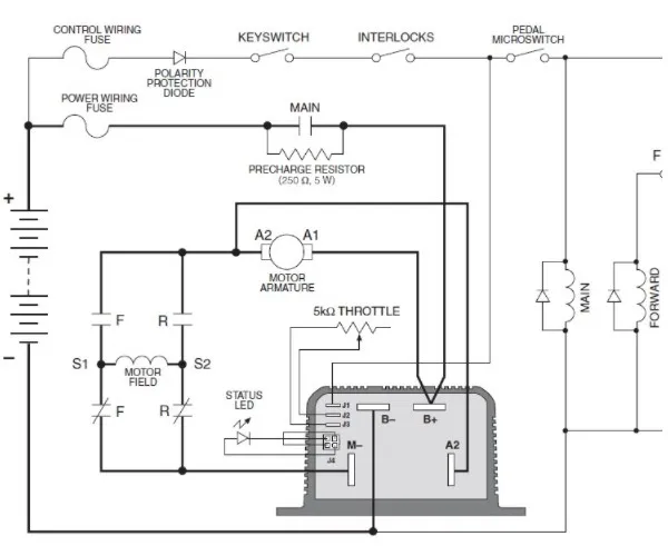
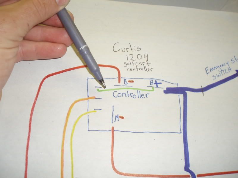
Fig. 3 Basic wiring diagram, Curtis 1204M/05M motor controller. 2 — INSTALLATION & WIRING: Standard Wiring Diagram CONTROLLER WIRING: BASIC CONFIGURATION A basic wiring diagram for the 1204M/05M controller is shown in Figure 3. The throttle shown in the diagram is a 2-wire potentiometer; voltage throttles can also be used.
WIRING DIAGRAM 1232 AC Induction Motor Controller PUMP CONT DIGITAL DRIVER 7 J1-20 J1-30 ANALOG OUT (0-10V) B− Models 1232SE / 1234SE / 1236SE / 1238SE TYPICAL WIRING 1232 1234 1236 SERIES SERIESLogos Curtis MarCom 2014

Curtis controller wiring diagram
2 — INSTALLATION AND WIRING pg. 3 Return to TOC Curtis 1232E/34E/36E/38E & 1232SE/34SE/36SE/38SE Manual, os 31 – May 2017 2 — INSTALLATION AND WIRING MOUNTING THE CONTROLLER The outline and mounting hole dimensions for the 1232E/SE controller are shown in Figure 2a, for the
Curtis 1204 M 5203 Electric Dc Motor Sd Controller 36 48v 275a For 3kw Sightseeing Bus China And Lishui Made In Com. Curtis Controller Wiring Diagram 29. Diagram Curtis 1510 Controller Wiring Deli Lamontagnella It. Dc Motor Controller Upgrade. Curtis Programmable Dc Sepex Motor Controller Assemblage Model 1268 5403 36v 48v 400a With Foot Pedal ...
Curtis Speed Controller Wiring Diagram Curtis 1234 1236 or 1238 Ac Motor Speed Controller is one of the pictures that are related to the picture before in the collection gallery, uploaded by autocardesign.org.You can also look for some pictures that related to Wiring Diagram by scroll down to collection on below this picture. If you want to find the other picture or article about Curtis Speed ...
Curtis controller wiring diagram.
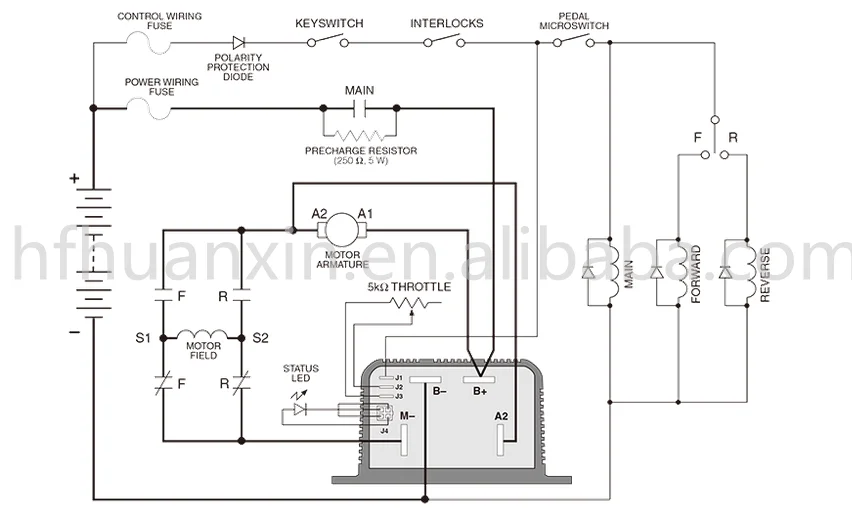
Fig. 4 Basic wiring diagram, Curtis 1204M/05M/09M/21M with active main contactor. 2 — INSTALLATION & WIRING: Standard Wiring Diagrams CONTROLLER WIRING: BASIC CONFIGURATIONS Two basic wiring diagrams are shown; they are identical except for the wiring at terminal J5. In the configuration in Figure4, the main contactor driver is active. In the ...
17 Feb 2009 — Fig. 3 Basic wiring diagram, Curtis 1234/36/38 motor controller. 2 — INSTALLATION & WIRING: Standard Wiring Diagram.134 pages
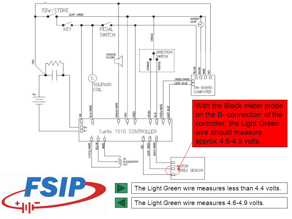
ELECTRICAL MAINTENANCE System controller, CURTIS 1703 Handset Operation The handset displays the controller’s model number, date of manufacture,and software revision code when first plugged in. Following this initial display, the hand- The optional universal Curtis handset allows you to set displays the Main Menu, which is the starting point program, test, …
Curtis 1268 controllers are separately excited motor speed controllers designed for ... This wiring is also shown in the standard wiring diagrams, Figs.68 pages
Circuit Diagram for Wesley. International Pack Mule Including. Options. 36-48V Stand-Up. Curtis. Controller Part Number EV-E189-48. Released July 20, 2012.
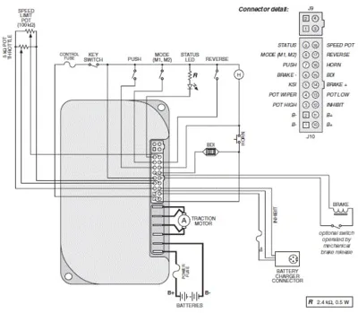
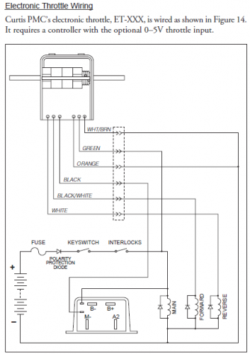
Push-on connectors for control wiring Familiarity with your Curtis PMC controller will help you to install and operate it properly. We encourage you to read this manual carefully. If you have questions, please contact the Curtis office nearest you.
Curtis Controller Wiring Diagram – wiring diagram is a simplified gratifying pictorial representation of an electrical circuit. It shows the components of the circuit as simplified shapes, and the knack and signal contacts in the company of the devices.
Curtis 1204 Controller Wiring Diagram | Wiring Library – Curtis Controller Wiring Diagram Wiring Diagram contains several in depth illustrations that display the relationship of various things. It consists of guidelines and diagrams for various varieties of wiring techniques as well as other things like lights, home windows, and so forth.
4 Basic wiring diagram, Curtis 1204M/05M/09M/21M with active main contactor. 2 — INSTALLATION & WIRING: Standard Wiring Diagrams. CONTROLLER WIRING: BASIC ...
Like all Curtis controllers, the 1204M and 1205M offer superior operator ... 3 Basic wiring diagram, Curtis 1204M/05M motor controller.38 pages
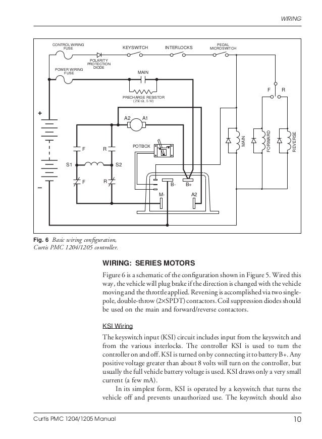
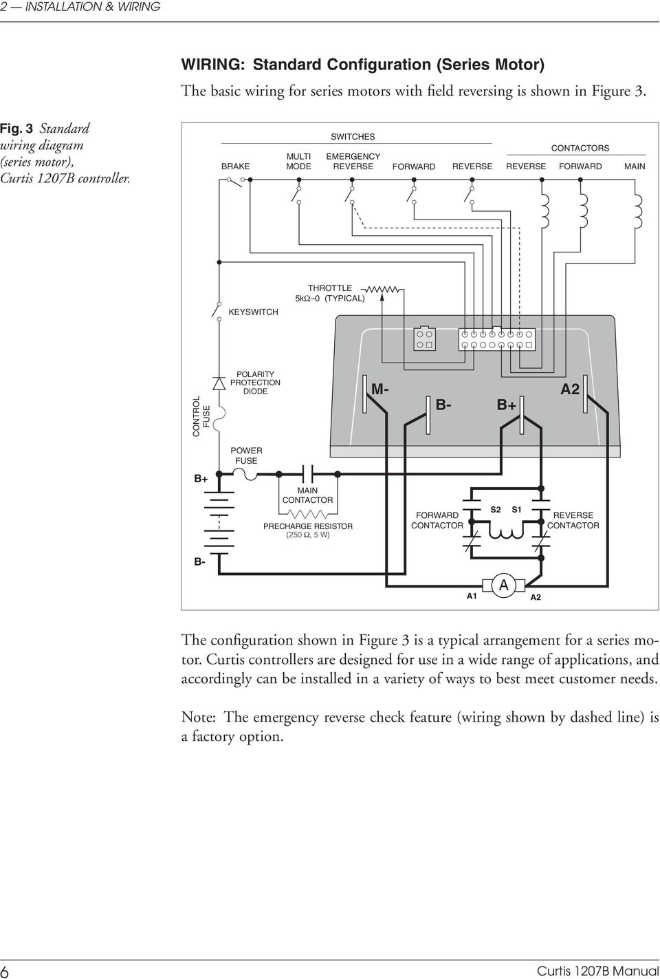
FIG. 3: Standard wiring diagram (series motors), Curtis PMC 1207 controller .....6 FIG. 4: Compound motor wiring diagram, Curtis PMC 1207 controller .....8 FIG. 5: Wiring for 5kΩ–0 throttle (1207 controller).....10 FIG. 6: Wiring for 20kΩ potentiometer
21.12.2010 · CURTIS 1234, 1236 OR 1238. AC INDUCTION MOTOR/ CONTROLLER. Page 2 of 20 EZ-GO Curtis Controller Installation 1. Disconnect Negative Battery Cable, Disconnect Positive Battery Cable. 2. Disconnect all Motor and Controller wires. 3. Remove original Motor, Controller & Reversing Switch (remove controller-mounting plate, if equipped). 4. Remove …

Michael golub -- electric truck
Nov 09, 2018 · Ezgo Txt And Curtis 1206 Wiring Diagram. E. 500 amp, 48 volt, Curtis series controller for Club Car with 5K-0 throttle (Fits 1996-up) Sale! Regularly 5. May 19, 2011 #2 I've never done a EZGO RXV but it should be pretty straight forward to set it at the private setting. EZGO Marathon/ Club Car DS Speed Controller 325 Amp - 0-5K With HPD (36-48V, 325A) 9. …
1228 2430 curtis motor controller 24 v 70a|atv parts & aksesoris ...
Alternate power wiring, for reversing with ... Block diagram, Curtis 1204/1205 controller . ... Pot fault circuit shuts off controller if pot wires open.52 pages

Genuine curtis 1228 series curtis 1228 2901 24v 110a d.c. motor ...
Manuals & Downloads. Troubleshooting. SERVICE DE SOUTIEN PRODUIT. Manuels et Téléchargements.

1274 wiring diagram | pdf | vehicles | electric motor
Curtis 1239 Controller Wiring Schematic FOR SOFTWARE VERSIONS GENERIC 5.32 AND HIGHER SINGLE AND DUAL MOTOR APPLICATIONS Click on the above graphic to open PDF file. Motorcycle Generic Wiring Schematic Click on the above graphic to open PDF file. Directions; Version 5.0 to 5.09; Version 5.11 and 5.12; Version 5.13; Version 5.14; New Generic …
Manual de controlador dc da curtis
21.11.2018 · Ezgo Curtis 1205m Controller Wiring Diagram; 4ac Engine Wiring Diagram; Dr Dre Beats Wiring Diagram; Gy20074 Wiring Diagram; Escalade 5th Wheel Rv Tail Light Wiring Diagram; Pioneer Deh X1910ub Wiring Diagram; Wiring Diagram Forboss Model Bv9384nv; 1996 Ford Windstar Fuse Box Diagram; 1986 Fxr-f Wiring Diagram; Kymco Venox 2005 …

Curtis pmc 1207 & 1207a multimode motor controllers manual - pdf download
12.07.2017 · Fleetwood Rv Wiring Diagram 1983 Chevy Wiring Diagram 2019 Thor Motor Coach Omni Super C Sv34 For Sale In Oahu Hi Cl A Motorhome Wiring Diagram Daily Update Wiring Diagram Thor Solar Panel Installation For Rvs Trailers Am Solar Class C Motorhome Thor Motor Coach What S The Deal With The Battery Disconnect Switch Thor Motor Coach …
36 volt curtis dc motor controller for electric mobility scooter ...
Can be used with any ebike brushless motor for those comfortable with wiring an ebike controller. but for the motor suggest you use the 72V motor , it can let motor put-out full power. 48V 30AH/60V 30AH/ 72V 30AH 7-Light Electric Vehicle Battery Charger Adapter 1 Budget Screamer (28KW, 72V Brushed) This kit can put out the most power per dollar of all the …
Dc motor controller upgrade.

Curtis dc motor controller 1204m-5305 36v/48v 325a for eclctric ...

Curtis/ ipm system (32kw brushless)
Curtis e-z-go 48v 250a (its) controller 1206hb5201
New guy here wanted to introduce myself / taco minibike project ...
Club car iq technical information - ppt video online download

Curtis brushless controllers

Genuine curtis 1266 curtis 1266-5351 curtis 1266r-5351 36v 48v ...
Curtis dc pengontrol motor 24v/36v,suku cadang kereta golf,kontrol ...

Curtis 1234, 1236 or 1238 ac motor speed controller programming ...
Curtis dc electrical motor controller 1204m-5203 for ezgo club car ...

Curtis 1205m-4601 controller 24v 36v 500a dc motor controller for ...

Curtis controller dc electric motor controlador 24v 36v 275a for ...

Curtis programmable dc sepex motor controller 1266a-5201 36v/48v ...

Https://www.nocoev.com/ | curtis programmable motor speed ...
Curtis controller wiring diagram - ebooks and journals

Dc series motor controller assemblage, curtis 1204m-5203, 36v ...

Dc series motor controller assemblage, curtis 1204m - curtis dc ...
Help! need expert to integrate two diagram for dc golf cart ...
Curtis 1204-020 160a controller help! | diy electric car forums

Kontroler motor seri curtis 1204 curtis 1204m-4201 curtis 1204m 24v 36v 275a asli
Curtis controller 1205-205 36-48v 350 amp 0-5v throttle input. | v ...
Multimode electronic motor controller - pdf free download
Curtis 1243-4220 200a controller assembly combo accessory packs 19 in 1 contactor meter throttle fuse emergency switch

Curtis 1204 controller wiring diagram new | mitsubishi cars, car ...

Pengendali sepex elektrik pmc,36v 48v 275a kontroler mobil klub ...

Club car iq technical information - ppt video online download

36v / 48v - 500a curtis motor controller - china curtis controller ...
Stefan spännare: electric motor and curtis controller

Model 1228 - curtis instruments - pdf catalogs | technical ...
0 Response to "38 curtis controller wiring diagram"
Post a Comment