42 700r4 transmission speed sensor wiring diagram
700r4 speed sensor wiring diagram. Using a digital volt ohmmeter dvom measure the resistance ohmmeter function between the sensor terminals. The trans already has an electrical connection. The last way to identify if it s a 4l60 or a 700r4 is to look at the rear of the transmission for the aux tv cable. I m working on a 72 c i just finished ... Find the transmission dipstick and follow it to locate your transmission. The VSS will be a small sensor attached to your transmission by 2 wires and held in place by a bracket. It will also have a sliding pull tab on it. Look for a small, metal sensor surrounded by a metal bracket with a white and black wire connected to it.
if the speedo plug is a 2 wire hook up on your 700R4...one wire goes to ground the other goes to the signal in post of the electronic speedo. You will have to use the calibration button that came with your speedo. I have a 85 corvette 700r4 and a new SW wings series electronic speedo in my rpu. I did an 87 700R4 to a VDO electronic speedo in my ...

700r4 transmission speed sensor wiring diagram
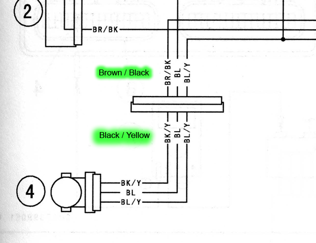
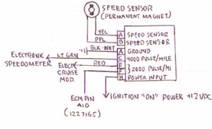
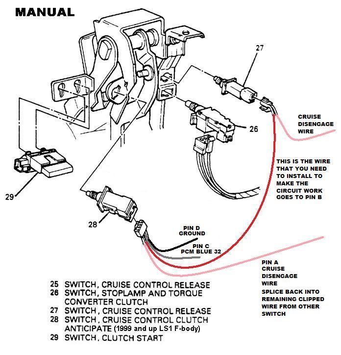
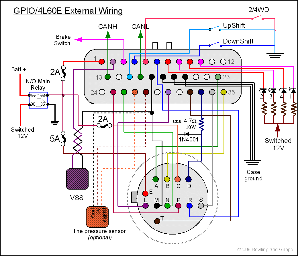
2-WIRE V.S.S.! GND FUSE - LOW SIDE + HIGH SIDE SPEED OUT (SEE CAUTION) DASH LIGHTING POWER SIG GND +12V GND Back of speedometer Engine Ground LAMP OUT LAMP +12V 12V IGNITION SWITCH FACTORY OR AFTERMARKET COMPUTER OR TRANS CONT. V.S.S. SPEED OUT LO SIG HIGH SIG Wiring Wiring Wiring w/ most OEM 3-wire V.S.S. (Vehicle Speed Sensor) w/ most OEM 2 ... 1990 Chevy 700r4 Transmission Electronic Speedometer Wiring Diagram An easy transmission to find, and to retrofit into your GM vehicle - TH R4 Because of the transmission's overdrive ratio 4th gear, the R4 also helped the driver's side of the transmission, and a sleeve for the speedometer gear is on and they use an electric control solenoid to ... 700r4 Transmission Speed Sensor Wiring Diagram. Harrietta Marchand. November 8, 2021. November 8, 2021. Parts Diagram For 4l80 E Transmission Automatic Transmission Dodge Diesel Chevy Transmission. 01 Sierra Turbo Build New Frame Page 20 Performancetrucks Net Forums Transmission Transmission Repair Sloppy Mechanics.
700r4 transmission speed sensor wiring diagram. 4l60e Wiring Diagram Best Of 700r4 Transmission For For. The Hydra-matic 4L60-E Technician's Guide is primarily intended for automotive technicians that have some familiarization with an automatic transaxle or transmission.Other persons using this book may find this publication somewhat technically complex if additional instruction is not provided. 700r4 Transmission Speed Sensor Wiring Diagram- wiring diagram is a simplified up to standard pictorial representation of an electrical circuit.It shows the components of the circuit as simplified shapes, and the capacity and signal links in the midst of the devices. 1,969 Posts. #4 · Feb 21, 2005. I have the Autometer elec speedo with a tremec 3550. I used a Ford T-5 sensor and gear. Got from my local Ford dealer. My old invoice lists the following that I purchased on that day: Part Number/Description: E9TZ-9E731-A Sensor 759193 $ 36.58. C1DZ-17292-A Ret-Spe 106646 $ .31 (I think this is a retainer) The 700R4, also known as Turbo Hydra-Matic, is a 4-speed automatic transmission that was launched by General Motors in the early 1980s. It is an upgrade to the 3-speed TH350 automatic transmission and older models of rear-wheel-drive cars. Also, the 700R4 transmission featured a 30% overdrive in 4th gear which brought about fuel economy.
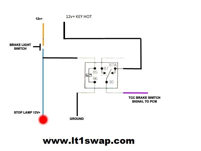
The B&M TH-700R4 is a specially modified transmission ... FIG. 3 Speed Sensor Controlled TCC Wiring FIG. 2 4th Gear Only TCC Wiring 2 B&M 70244 or 70248. ... for an example wiring diagram. The second approach is to install a speed sensing device (such as B&M P/N 70244 or 70248) ... 7 stock sensor gm part 15547452 and pigtail aftermarket part replaces gm 700r4 transmission controller attached images Discussion Starter · #1 · Sep 16, 2013. I'm working on a 72 C10. I just finished running a full American Autowire kit for the truck. I just need to hook up an AutoMeter electric speedo to my 700r. The trans already has an electrical connection. I pulled a connector to plug into the trans from the pull-a-part salvage. This is a 2 wire connection. 700r4 transmission wiring diagram. 700r4 transmission cooler line diagram you are welcome to our site this is images about 700r4 transmission cooler line diagram posted by brenda botha in 700r4 category on aug 02 2019. 1 oil pressure switch installation 1. External wiring from the oil pressure switch at the transmission leads to a dash switch ...
Part # Description Min Qty Price Qty; 100-00333: Vehicle Speed Sensor VSS T56 4L60E 4L80E Connector Pigtail for GM LT1 LT4 LS1 LS6 LS2 LS3 LS7 and many other VSS applications: $10.00 700R4 Transmission Speed Sensor Wiring Diagram from f01.justanswer.com. Effectively read a electrical wiring diagram, one provides to know how typically the components within the system operate. For example , in case a module will be powered up and it also sends out the signal of half the voltage and the technician would not know this, he would ... I'm at the last part on wiring up an AutoMeter Electric Speedometer to my 700r4. The transmission already has an electric sender connection on the tailhousing. I robbed the connector that plugs into it at the pull-a-part salvage. It's just a 2 wire connection. 1 ground & 1 signal. I just ran an entire American Autowire kit for the truck. 700r4 Wiring Schematic Wiring Diagrams. Wiring Th350c Lock Up Diagram Wiring Library. 700r4 Lockup Wiring Toggle Switch Best 700r4 Torque. Painless Wiring 60109 700r4 Transmission Torque Converter Lock Up Kit. 700r4 Transmission Speed Sensor Wiring Diagram Lockup Best. Lock Up 700r4 Manual Diagram Cashewapp Co.
The Speedo Does Go Through Ecm On A 92 Third Generation F Body Message Boards
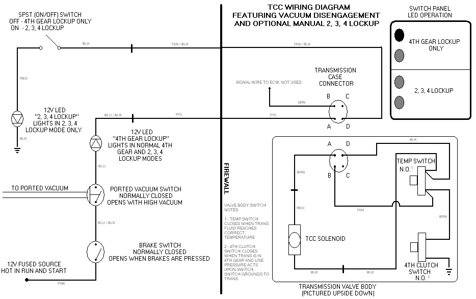
A transmission has a 31% overdrive and will produce a 30 to 40% increase in gas mileage on the road over a three speed transmission.Wiring a Lockup-Converter Pressure Switchto Chevy Trucks - Chevy Truck Parts. 1 thoughts on " 700r4 transmission lock up wiring diagram ...
4th Gen Lt1 F Body Tech Aids
Disengage the wiring harness connector from the VSS. 700r4 Transmission Speed Sensor Wiring Diagram wiring diagram is … Read more. Latest Posts. trailer wallpaper. 7 Pin Round Trailer Plug Wiring Diagram. 03 Sep, 2021 Post a Comment Socket and plug are keyed. If you have a 13 pin socket fitted to your vehicle adaptors to plug in so you can ...
No Ecm Tcc Lockup Diagram Third Generation F Body Message Boards
DOWNLOAD 700r4 Speedometer Wiring Diagram. Close DOWNLOAD. 700r4 Speedometer Wiring Diagram. Blog - electronic speedometer wiring diagram anything that moves for about 40 years now. What is an electronic speedometer and why would I need one?. ... The signal is a square wave but it's only going to be present on one lead from the speed sensor. Re ...

Lq9 To Np205 Vss Help Ls1tech Camaro And Firebird Forum Discussion
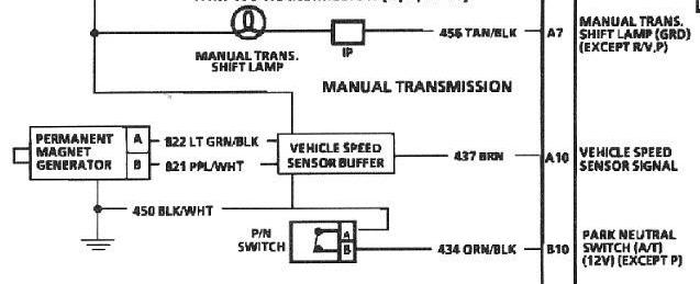
transmission, 1994 and newer rear drive cars with the automatic transmission 4. A 17 tooth per driveshaft revolution speed sensor used on 1993-1997 LT1 engines with the Borg-Warner 6-speed transmission. An 11 tooth reluctor ring is used on 1993 LT1 engines with the Borg-Warner wide ratio (3.35 First gear) 6-speed transmission.
Painlessperformance Com
1992 Camaro 5 Speed Vss Wiring Diagram. Speed Sensor New Chevy Chevrolet Camaro Pontiac Firebird Caprice Fleetwood Buick TBI TPI Camaro Firebird R4 Auto or T5 5 Speed Manual. everyone said that if i take out ecu and harness, it wont effect speedo. camaro TPI does not have a BUFFER box it is BUILT INTO THE ECM.

700r4 Speed Sensor Ebay
700r4 Transmission Speed Sensor Wiring Diagram 700r4 torque Converter Lockup Wiring Diagram Wiring Library is one of the pictures that are related to the picture before in the collection gallery, uploaded by autocardesign.org.You can also look for some pictures that related to Wiring Diagram by scroll down to collection on below this picture. If you want to find the other picture or article ...
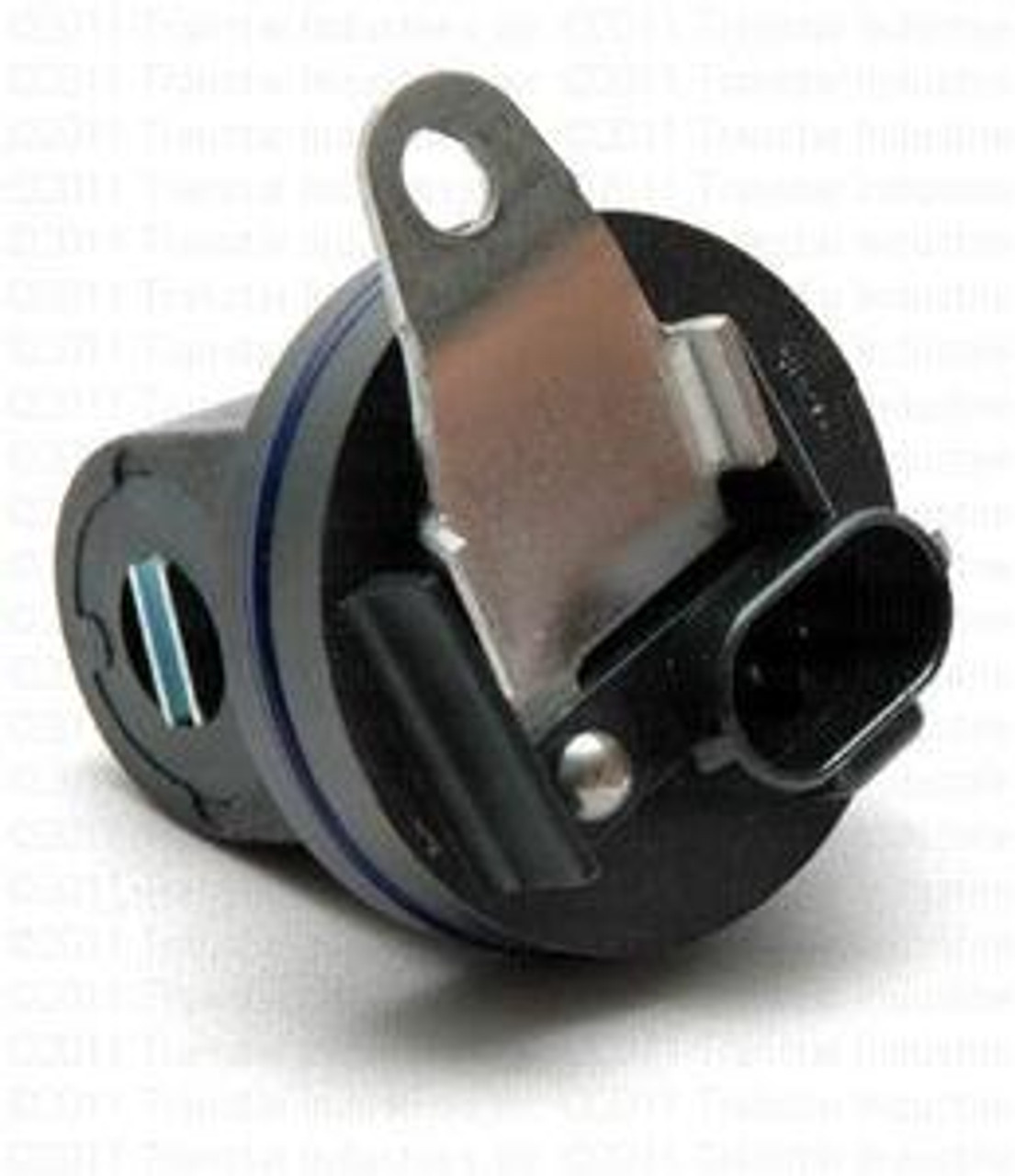
4l60e 700r4 Transmission Speed Sensor Vss Replaces Ac Delco 8673299 Fits 82 E 96 Transmission Parts Distributors
VEHICLE SPEED SENSOR CONNECTOR WIRING HARNESS PLUG 4L60 LT1 R4 4L60E. Motoparty Vehicle Speed Sensor VSS Connector Pigtail Harness For T5 R4 4L60 4L60E GM Speed Sensor PT,Fog Light Connector/VSS Vehicle Speed Sensor/Transmission Output Shaft Sensor,3PCS. by MotoParty. $ $ 21 FREE Shipping on eligible orders. Find great deals on eBay for r4 wiring.
2008 2010 Zx10r Speed Sensor Zzrbikes
Three-wire signals are usually found in newer aftermarket. speedometer kits and they have three wires. One wire is a reference. power, one wire is the ground, and the third wire is the signal. 2. Use a mulitmeter to test. One-Wire Signals. (Figure 1.) Most one-wire signals can be measured with a multimeter set to DC.
Wilbo666 Toyota Speed Sensors
3 Gang Dimmer Switch Wiring Diagram Uk; 700r4 Transmission Speed Sensor Wiring Diagram; 7 Wire Semi Trailer Wiring Diagram; 48 Volt Ezgo Golf Cart Wiring Schematic; 1995 Ford Escort Cooling Fan Wiring Diagram; 2004 Honda Element Radio Wiring Diagram; 7 Way Trailer Plug Wiring Diagram Heavy Duty

700r4 Can You Idnentify This Wire Plug Third Generation F Body Message Boards
The 700r4 transmission was not electronically controlled yet; it was hydraulic pressure controlled with a TV cable, which acted as a throttle position sensor to control the gear shifting. In 1991~ the 700r4 transmission was replaced by the popular transmission 4L60.

Using An Electronic Speedo With Tbi And 700r4 The 1947 Present Chevrolet Gmc Truck Message Board Network
Nov 5, the wiring harness for the transmission got pulled out. my speedometer will have to connect the wires back to the vss/vehicle speed sensor., R4, Turbo, Turbo, 4L60 (non-electronic) and manual transmissions. Includes (VSS) vehicle speed sensor wiring, transmission wiring (if.Sep 24, · Wiring AutoMeter electric speedometer to r4.

128k High Frequency Gm Pulse Generator
700r4 Transmission Speed Sensor Wiring Diagram. Harrietta Marchand. November 8, 2021. November 8, 2021. Parts Diagram For 4l80 E Transmission Automatic Transmission Dodge Diesel Chevy Transmission. 01 Sierra Turbo Build New Frame Page 20 Performancetrucks Net Forums Transmission Transmission Repair Sloppy Mechanics.
Aftermarket Speedo Buffer West Coast Fieros Forum
1990 Chevy 700r4 Transmission Electronic Speedometer Wiring Diagram An easy transmission to find, and to retrofit into your GM vehicle - TH R4 Because of the transmission's overdrive ratio 4th gear, the R4 also helped the driver's side of the transmission, and a sleeve for the speedometer gear is on and they use an electric control solenoid to ...
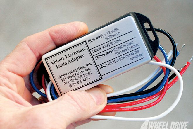
Electronic Ratio Adapter Era To Adjust Electronic Speedometers Patc Transmissioncenter Net
2-WIRE V.S.S.! GND FUSE - LOW SIDE + HIGH SIDE SPEED OUT (SEE CAUTION) DASH LIGHTING POWER SIG GND +12V GND Back of speedometer Engine Ground LAMP OUT LAMP +12V 12V IGNITION SWITCH FACTORY OR AFTERMARKET COMPUTER OR TRANS CONT. V.S.S. SPEED OUT LO SIG HIGH SIG Wiring Wiring Wiring w/ most OEM 3-wire V.S.S. (Vehicle Speed Sensor) w/ most OEM 2 ...
Wiring Harness Information
Technical 700r4 Od Question The H A M B

Can You Help Me With A Wire Diagram From A 4l80 Chevy Trans To A 700r4 Trans
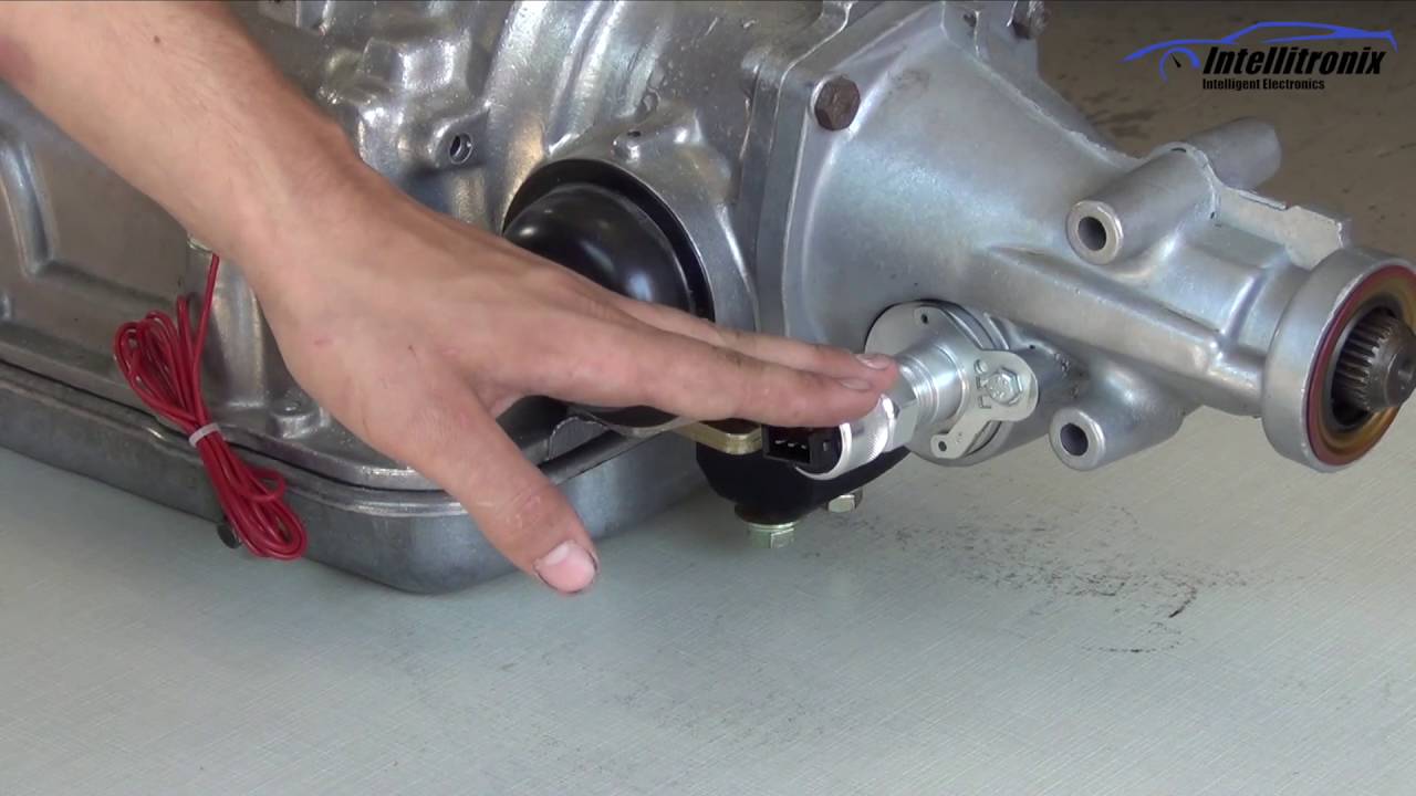
Install Of Speed Sensor Youtube

1994 Chevy 1500 4wd W 4l60e Tranny Would Like To Swap In A 700r4 Question E Plug In On The4l60 Verses The Square 4

Easy Ways To Test A Vehicle Speed Sensor With A Multimeter

If You Have A P0717 Input Turbine Speed Sensor Circuit No Signal Trouble Code This Post Will Help You Understand What It Is And How To Fi Sensor Speed Turbine
Overdrive Options The 700r4 And The 4l60e Debate Goes On
Digital Cruise Darth Fiero Pennock S Fiero Forum

Painless 60109 700r4 Transmission Torque Converter Lock Up Kit
Manual Conversion Wiring Ls1tech Camaro And Firebird Forum Discussion

700r4 Trans Wiring Transmission Problems

700r Trans Fix It Tips
Quick Tech Tip Mechanical Vs Electrical Vss For A 700r4 Transmission Youtube
Trans Parts Online 700 4l60e Transmission Parts

4l60e To 4l80e Wiring Swap Performancetrucks Net Forums

Attesa Ets Pro Electrical Circuit Diagram Nissan Skyline Gt R S In The Usa
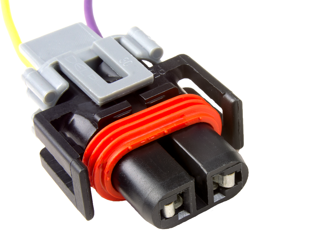
Vehicle Speed Sensor Vss 700r4 4l60e Connector Pigtail Efi Connection Llc
Megashift 4l60e

Diagram Based 700r4 Tcc Lockup Diagram Completed
Need Help Wiring A Speed Sensor Chevrolet Forum Chevy Enthusiasts Forums

Transmission Wiring Can I Get A Chevy 4l60e Diagram Please Best Of With For 4l60e At 4l60e Transmission Wiri Chevy Transmission Electrical Diagram Transmission
700r4 Wiring V Manual Wiring In Gm Tbi Swap Pirate 4x4
Gm 700r4 Manual Torque Converter Lockout Hot Rod Forum

Ebook Databases
Vehicle Speed Sensor Wiring 35 Images Repair Guides Automatic Transmission 1999 Vehicle Tpi 700r4 Vehicle Speed Sensor Vss Adapter Wiring Harness Repair Guides Vehicle Speed Sensor 2001 Vehicle
1

700r4 Speed Sensor 700r4 Speedometer Gear Types
0 Response to "42 700r4 transmission speed sensor wiring diagram"
Post a Comment