40 free body diagram torque
Produce a free-body sketch of the shaft. Replacing the various associated components with their equivalent load/torque components; Produce a bending moment diagram for the xy plane and the xz plane (x = shaft axis direction). Note: The resulting internal moment at any point along the shaft = M x = Sqrt (M xy 2 + M xz 2) Produce a torque diagram. Answer to F la R Free-body diagram of reaction torques. Math; Advanced Math; Advanced Math questions and answers; F la R Free-body diagram of reaction torques Supplied Applicable Formule for Question 1 R + y wa {wines 1- d Roller in contact with flank AB 1 = (R+) - (R+ r) w(R+ r) soc tan 0./ =wR+ r.)(2 nocle-sec ) tan dina 8 = angle turned by com for roller pt.
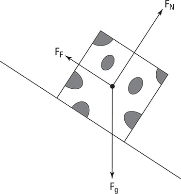
Figure 5.32 (a) The free-body diagram for isolated object A. (b) The free-body diagram for isolated object B. Comparing the two drawings, we see that friction acts in the opposite direction in the two figures. Because object A experiences a force that tends to pull it to the right, friction must act to the left. Because object B experiences a component of its weight that pulls it to the left ...
Free body diagram torque
Free body diagrams • A free body diagram shows a body isolated from other bodies • All external forces and torques acting on it are shown To solve for a body in equilibrium: 1. Decide on the body of interest 2. Draw a diagram of the body isolated from other bodies in contact with it 3. Show all forces and torques acting on the body Download scientific diagram | Free body diagram for the calculation of the joint force and torque of the upper trunk seg- ment. from publication: Kinetic ... what does a free body diagram involving torque look like? This is a free body diagram of a yo-yo resting on a table. The force of gravity acting on the yo-yo (green arrow) is pulling downward on the yo-yo as it would on any object in ideal circumstances.
Free body diagram torque. upward force by pivot. • rod is still subject to the same forces. • no change to free body diagram. • it will rotate, but free body diagram misses this!152 pages In this video, we solve a torque diagram without having to use equations. By simply looking at the external loadings, we can easily draw the internal torque... Draw a free-body diagram of the shaft on either side of the cut Use a static-equilibrium equation and the following sign convention to obtain the internal torque at the section Sign Convention Using the right-hand rule, the torque and angle of twist will be positive, provided the thumb is directed outward from the shaft when the The 50N.m torque is balanced by the two torques of 35 and 15 N.m at A and B respectively. Therefore, the body as a whole is in equilibrium. Step 2 We obtain the free body diagram of the part of the shaft, by passing a plane perpendicular to the shaft at any point between A and B. So we have Σ M x = 0, this implies T AB = 35N-m.
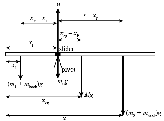
Free Body Diagrams for Torque situations usually include a weight for the object experiencing the torque, various or a single support force, and any other pushes or pulls that are acting to keep the object in equilibrium. Below is an example of a slightly more difficult free body diagram that also demonstrates two sets of "couple" forces. And, of course, you've used a "torque" wrench. So, whether it's a moment, couple, or torque, the result is the same: Something is being twisted.) The first problem an engineering student is given is usually a horizontal flag pole sticking out of a building. To make a free body diagram of the flag pole, he "removes" the building and replaces it ... (b) Use the free-body diagram to write a correct equilibrium condition for force components in the y-direction. (c) Use the free-body diagram to write a correct equilibrium condition for torques along the axis of rotation. Use to evaluate torque magnitudes and senses. A free-body diagram can be drawn very simply, with squares and arrows, or you can make it much more complex. The only requirement is that you or someone else looking at it should be able to understand what the diagram is telling. A free-body diagram (FBD) is a representation of a certain object showing all of the external forces that acts on it.
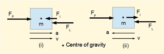
8 days ago — Torque Diagrams. To investigate situations in static equilibrium more thoroughly, you can make use of an extended free-body diagram that shows ... But as a piece of advice, when you put a free body diagram up for comments, as Rb stated, you must show it in equilibrium and the out of plane forces and moments must be shown in the diagram Anyway, in summary your free body on the shaft should read. 200nM ccw, 200nm cw ,wihth an asterisk 96*9,8n upwards and 98,6 downwards with an asterisk. The following free body diagrams illustrate the concepts of inertia forces and torques. (note: the terms inertia torque and inertia moment are synonymous) In diagram (i) F P is the force which must be applied to accelerate mass m at a m/s 2 against a constant load force F L (ignoring friction). (b) Use the free-body diagram to write a correct equilibrium condition Equation 12.11 for force components in the y-direction. (c) Use the free-body diagram to write a correct equilibrium condition Equation 12.9 for torques along the axis of rotation. Use Equation 12.10 to evaluate torque magnitudes and senses.
Free-body diagrams and torque Thread starter Niles; Start date Dec 23, 2007; Dec 23, 2007 #1 Niles. 1,868 0. Homework Statement Two friends are carrying a crate of mass 200 kg up a flight of stairs. The crate has length 1.25 m and height 0.50 m, and its center of gravity is at its center. The stairs make a 45.0 angle with respect to the floor.

Ppt What Is The Torque T Due To Force F F 100n Distance To F R F 1m Q 30 O Powerpoint Presentation Id 2487342
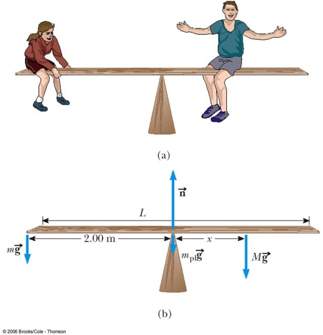
The Free Body Diagram looks like this: The upwards force R balances the downwards Weight. With only those two forces the beam will spin like a propeller! But there is also a "turning effect" M called Moment (or Torque) that balances it out: Moment: Force times the Distance at right angles.
Looking at the free body diagrams for each gear, there is a normal force acting on each gear. The normal force acts at an angle from tangent called the pressure angle, Φ. In the case of the two gear set-up, there are opposing torques as well. For idler gears, there is no torque, but the normal forces from all gear meshes balance out.
Equilibrium is a special case in mechanics that is very important in everyday life. It occurs when the net force and the net torque on an object or system are ...
A) Draw a free-body diagram. Show the torque reactions at supports A and C in the correct direction for resisting the applied torque, T. From your free-body diagram, write the equilibrium equation for the torques. Express the torsional equation of equilibrium for the shaft in terms of TA, and TC. B)
468. 1. Homework Statement: Draw a FBD, determine the largest torque, T1, and find shear stresses in CD and DE. Relevant Equations: Method of sections, static equilibrium. shear stress=Tc/J. I wish to draw a proper free-body diagram for this shaft. However, my FBD does not agree with the solutions manual.
The torque from is the cross product of the radius vector with. A free body diagram is a picture showing the forces that act on a body. Draw a fbd of the 1000 lb weight. Physicslab Freebody Diagrams 4 Free Body Diagram Inclined Plane Pulley Luxury Free Body Diagram For Solved Load P Is 800n Draw A Free Body Diagram Of Pulley
To create the torque diagram for a shaft, we will use the following process. Solve for all external moments acting on the shaft. Draw out a free body diagram of the shaft horizontally, rotating the shaft if necessary, so that all torques act around the horizontal axis. Lined up below the free body diagram, draw a set of axes.
This is something of a tricky problem, because you have to draw the free-body diagram of the entire ladder to figure out the normal forces, and then draw the free-body diagram of one half of the ladder to complete the solution. This is also what makes it a good example to look at, however. Consider first the free-body diagram of the entire ladder.
Drawing Free-Body Diagrams. Free-body diagrams are diagrams used to show the relative magnitude and direction of all forces acting upon an object in a given situation. A free-body diagram is a special example of the vector diagrams that were discussed in an earlier unit. These diagrams will be used throughout our study of physics.
Basic static equilibrium examples that emphasize drawing the free body diagram, choosing an axis, and evaluating torque without bothering to work out the num...
Torque and Angular Momentum of a Particle The figure below shows a fixed coordinate system OXY Z containing a mass m moving with velocity v, having momentum p , and being acted upon by a resultant force, f . X Y Z O ... The free body diagram depicting the torques on the body is shown below. Note the directions of the unit
Here, the free-body diagram for an extended rigid body helps us identify external torques. Example. The Torque Balance. Three masses are attached to a uniform ...
Torque Free Body Diagram. torque relationship between force f torque τ linear momentum p and angular momentum l in a system which has rotation constrained in one plane only forces and free body diagrams basics mrwaynesclass identify the force acting on a body identify the direction of each acting force and draw vectors representing the forces create a pair of equations from
Free body diagram at θ 1: Free body diagram at θ 2: There are 4 torques acting: The external torque, τ a, clockwise. The torque due to K r.. If θ 1 increases (counterclockwise), K r causes a clockwise torque on J 1.; The resulting torque is K r ·θ 1, clockwise.; The torque due to B r1.. If θ 1 increases, the resulting torque on J 1 is B r1 ·ω 1 in the clockwise direction.
DD.3.1 Gyroscopes 1 - Free Body Diagrams, Torque, and Rotating Vectors Course Home Syllabus About the Team; Readings Assignments Review: Vectors Lesson 0: Vectors [0.1 - 0.6] Week 1: Kinematics Week 1 Introduction ...
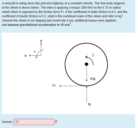
what does a free body diagram involving torque look like? This is a free body diagram of a yo-yo resting on a table. The force of gravity acting on the yo-yo (green arrow) is pulling downward on the yo-yo as it would on any object in ideal circumstances.
Download scientific diagram | Free body diagram for the calculation of the joint force and torque of the upper trunk seg- ment. from publication: Kinetic ...
Free body diagrams • A free body diagram shows a body isolated from other bodies • All external forces and torques acting on it are shown To solve for a body in equilibrium: 1. Decide on the body of interest 2. Draw a diagram of the body isolated from other bodies in contact with it 3. Show all forces and torques acting on the body









0 Response to "40 free body diagram torque"
Post a Comment