40 draw a top down diagram of your setup from part e
(3.5) Draw top-down diagram of your setup from part E This diagram should include: The cardinal directions (N,SE,W) The direction of current in the wires ...5 answers · 2 votes: Two very long wires run parallel to the $z$ -axis, as shown in the figure. They each ... To set up the equilibrium conditions, we draw a free-body diagram and choose the pivot point at the upper hinge, as shown in panel (b) of (Figure). Finally, we solve the equations for the unknown force components and find the forces. Figure 12.17 (a) Geometry and (b) free-body diagram for the door.
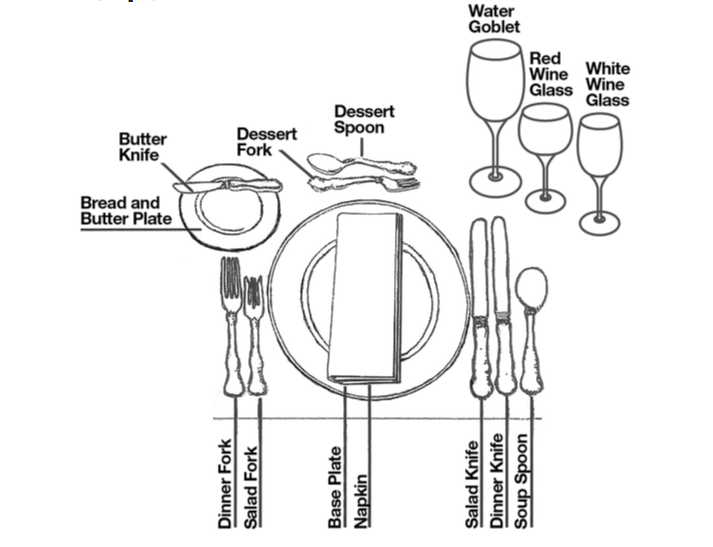
Your event will feature more than just banquet tables, of course. There might be pedestal rounds for special items, buffet tables, a head table, a stage or podium, a dance floor, a DJ or band, a bar, or a cocktail area with hightops. Add these to your event diagram to get a sense of your usable seating area and how the event as a whole will flow.

Draw a top down diagram of your setup from part e
Barry Wayne Lavay, Ronald W. French, Hester Henderson · 2006 · Sports & RecreationHighlight all of the data . 3. Go to Insert and then Chart . Select an XY ( Scatter ) and highlight the third graph down on the left side . Click Next . 4. Reading Time: 7 min Building your diagram by using layers allows you a lot more flexibility - you can switch between different views of your diagram, group related elements and protect them from being modified when you work in a different layer. In this exercise, you'll create a diagram in a top layer, following an image 'template' that you paste into the background layer. 4.0 Building Shear and Moment Diagrams. In the last section we worked out how to evaluate the internal shear force and bending moment at a discrete location using imaginary cuts. But to draw a shear force and bending moment diagram, we need to know how these values change across the structure.
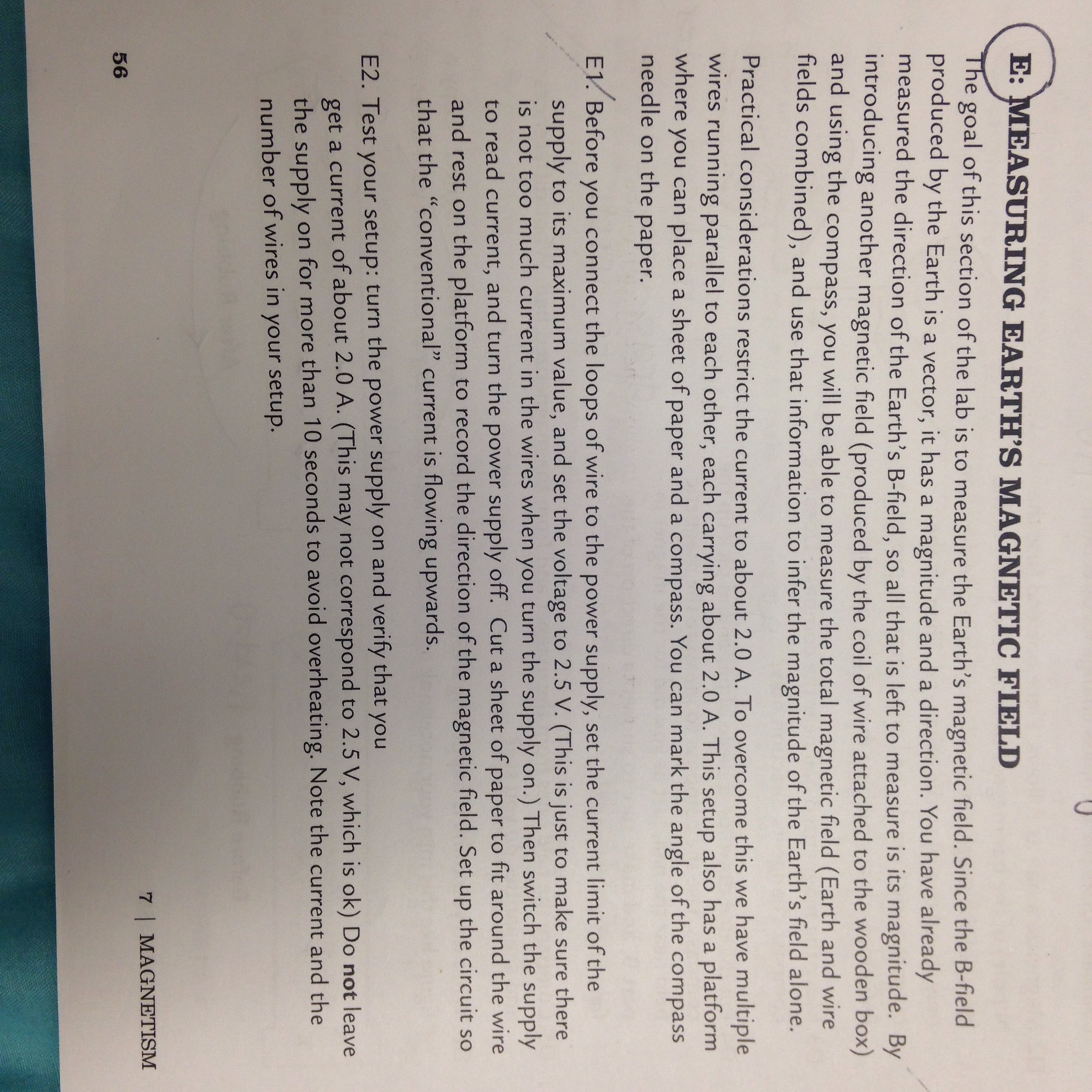
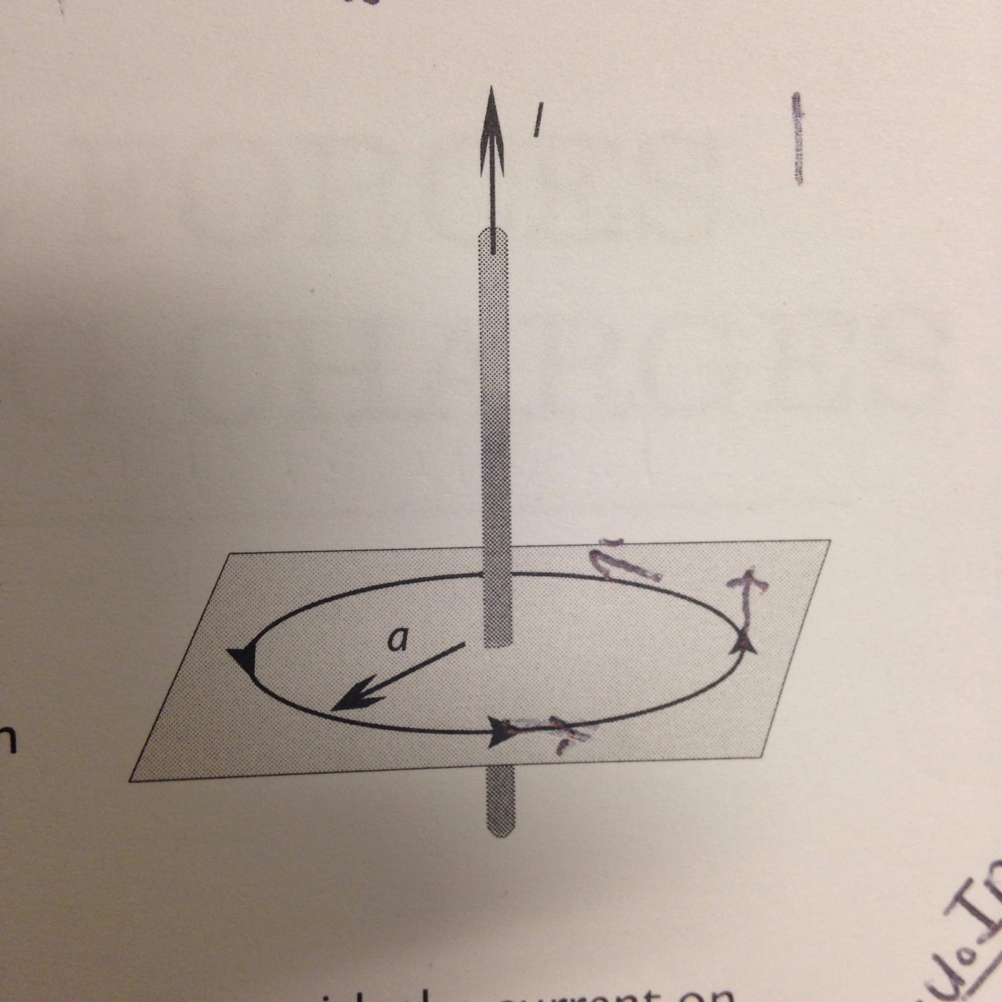
Draw a top down diagram of your setup from part e. Draw a top-down diagram of your setup of image provided: I is current passing through wire arrows are vectors of compass pointing. Subject: Physics Price: 3.85 Bought 3. Share With. Draw a top-down diagram of your setup of image provided: I is current passing through wire arrows are vectors of compass pointing. Tag: draw a top down diagram of your setup from part e. Latitud Condominium Design, the project that translates the feeling of being in the right place. (3.5) Draw a top-down diagram of your setup from part E. This diagram should include: a. The cardinal directions (N,S,E,W) b. The direction of current in the wires c. The direction of the compass needle d. A vector representing the Earth's magnetic field e. A vector representing the wire's magnetic field at the location of the compass f. Click on the Network Diagram header in the top left corner of the screen. A pop-up screen opens, type the name of your diagram in the text box and click OK. The name of your network diagram appears in the top left corner of the screen. 3. Remove existing elements that you don't need on your diagram.
The diagram shows part of the circulatory system. (a) Name the types of blood vessel labelled A, B and C on the diagram. ... Some students set up water cultures to find out how plants use nitrates. They had two sets of nutrient solutions. A full solution provided the plant with all the required nutrients. ... Draw a ring around your answer. 1. (3.5) Draw a top-down diagram of your setup from part E. This diagram should include: a. The cardinal directions (N,S,E,W) b. The direction of current in the wires c. The direction of the compass needle d. A vector representing the Earth's magnetic field e. A vector representing the wire's magnetic field at the location of the compass f. DATA (3):(a) Draw a top-down diagram of your setup of image provided: I is ... (N,S,E,W)Use your measurements from part E to calculate the strength of the ...1 answer · Top answer: Remember the geographic north pole is actually a magnetic south—that's why the north pole of a compass needle points to it.Use right-hand rule ... desirable to draw the V-diagram below the FBD of the entire beam, and then draw the M-diagrambelow the V-diagram. The bending moment and shear force diagrams of the beam are composites of the V and M diagrams of the segments. These diagrams are usually discontinuous, or have discontinuous slopes.
Learn how to create an Entity Relationship Diagram in this tutorial. We provide a basic overview of ERDs and then gives step-by-step training on how to make ... out of danger during let-down. Never draw a bow with a peak weight above your comfort level. Always use a wrist sling when drawing a bow. d. Never modify any part of the bow or its components by drilling extra holes or removing material. This voids the warranty and presents safety problems. e. Figure 5.32 (a) The free-body diagram for isolated object A. (b) The free-body diagram for isolated object B. Comparing the two drawings, we see that friction acts in the opposite direction in the two figures. Because object A experiences a force that tends to pull it to the right, friction must act to the left. Because object B experiences a component of its weight that pulls it to the left ... representing motion, drawing motion diagrams and drawing graphs. We'll do this for motion with constant velocity - motion in a constant direction at a constant speed. EXPLORATION 2.3A - Learning about motion diagrams A motion diagram is a diagram in which the position of an object is shown at regular time intervals as the object moves.
Download Center. All-in-one diagramming tool for creating over 280 types of diagrams with no hassle. Collaborative and versatile mind mapping tool to capture, organize and share ideas visually. Intuitive Gantt Chart maker to schedule, manage, and track your projects in real-time. Beginner-friendly design tool to help create visually striking ...
In the space provided on the worksheet, sketch and carefully label a diagram of the meter stick and the 200-gram mass. Show all the torque-producing forces. Remember that the weight of the meter stick acts at its center of gravity. Indicate on your diagram the directions (clockwise or counterclockwise) of each torque.
Mark Meysenburg · 2016 · ComputersSince the paddle just moves up and down, we don't need to do anything with the ... Based on the diagram we drew in Figure 6.6, the top collision variable is ...
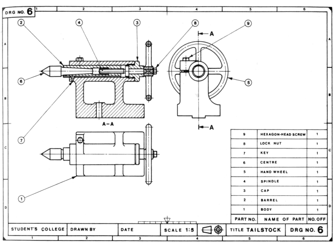
TOP View r Front View Right Side View Using the Top View shown in Fig. 2-8 as the Right-Side View, make a second sketch and compare it with Fig. 2-9. The three-view drawings which have been discussed are generally accepted as standard in the United States and TOP View On squared block paper, make a three- view drawing of the concrete block with
A functional, top-down organizational chart reflects a traditional business structure. This structure shows the C-Suite at the top, followed by other senior management, middle managers, and so on. The structure is divided into traditional departments like IT, marketing, finance, human resources, and operations based on everyone's functional ...
You can also try an animated diagram template, in which tabs are revealed one by one. Microsoft's animated diagram templates include an animated flower slide, an animated scale, and many others. Used alone or as part of a presentation, diagram templates give your story more impact to leave a greater impression on your audience.
• An entity type E (or a relationship type R) has attributes representing the structural (static) properties of E (or R resp.). • An . attribute . A is a mapping from E (or R ) into a Cartesian Product of n values sets, V. 1 V. 2 … V. n . • If n 2 , then we call attribute A a . composite attribute, otherwise (i.e. when n=1) call it a
The easiest way for Confluence teams to collaborate using diagrams ... More installs than all Confluence diagramming apps combined; Best-in-class security.
Transcribed image text: 1. (3.5) Draw a top-down 2D diagram of your setup in part E (imagine looking from above). This diagram should include a. The cardinal directions (N,S,E,W) b. The direction of current in the wires (8 for into, and O for out of the page) c. The direction of the compass needle (an arrow pointing to its north) d.
Draw a top down diagram of your setup from part e this diagram should include. You dont have to rely on your employees remembering the extra steps of saving and storing the diagrams in an appropriate and central location. In your mind draw a boundary around the fish tank including the waterto define it as your system.
Drawing Free-Body Diagrams. Free-body diagrams are diagrams used to show the relative magnitude and direction of all forces acting upon an object in a given situation. A free-body diagram is a special example of the vector diagrams that were discussed in an earlier unit. These diagrams will be used throughout our study of physics.
You can use colors to classify similar entities or to highlight key areas in your diagrams. Drawing ER Diagrams Using Creately. ... Draw the ";E-R" for the supplier and parts database. can i get the ER diagram for this. 20.03.2014 - reply. ... on top of the ballon u can write the entity names. 07.11.2013 - reply.
i. Draw a diagram of the experimental setup of the board and block. In your diagram, indicate each quantity that would be measured and draw or state what equipment would be used to measure each quantity. ii. Describe the overall procedure to be used, including any steps necessary to reduce experimental uncertainty.
Make sure you represent both the magnitude and direction of the electric field adequately. Note that the number of lines into or out of charges is proportional to the charges. (a) Draw the electric field lines map for two charges and situated 5 cm from each other. (b) Draw the electric field lines map for two charges and situated 5 cm from each ...
Let's apply the problem-solving strategy in drawing a free-body diagram for a sled. In Figure(a), a sled is pulled by force P at an angle of [latex]30^\circ[/latex]. In part (b), we show a free-body diagram for this situation, as described by steps 1 and 2 of the problem-solving strategy.
(b) The diagram shows part of a magnetic field. (i) Two magnetic field lines have already been drawn. Draw more magnetic field lines on the diagram to show a uniform magnetic field. (3) (ii) Describe how you would change your diagram to show a stronger magnetic field. (1)
then to the lower right corner of the part in the front view. Press the ESC key when you have finished. Your drawing should look like the one on the right. Next we will dimension the holes and the rounds in the corners. Click on the dimension pull down and click on the "Diameter" button. Use this command to dimension both circles. R2.00
4.0 Building Shear and Moment Diagrams. In the last section we worked out how to evaluate the internal shear force and bending moment at a discrete location using imaginary cuts. But to draw a shear force and bending moment diagram, we need to know how these values change across the structure.
Reading Time: 7 min Building your diagram by using layers allows you a lot more flexibility - you can switch between different views of your diagram, group related elements and protect them from being modified when you work in a different layer. In this exercise, you'll create a diagram in a top layer, following an image 'template' that you paste into the background layer.
Barry Wayne Lavay, Ronald W. French, Hester Henderson · 2006 · Sports & RecreationHighlight all of the data . 3. Go to Insert and then Chart . Select an XY ( Scatter ) and highlight the third graph down on the left side . Click Next . 4.






/cdn.vox-cdn.com/uploads/chorus_asset/file/19915585/akrales_200421_3975_0049.jpg)










0 Response to "40 draw a top down diagram of your setup from part e"
Post a Comment