38 push button start diagram
one push button start stop relay. This is ON OFF switch circuit by using the single pushbutton switch. In this circuit used 2 relays. Make the connection as the given diagram. When you give the supply to the connection, the output load is in OFF. Once press the switch for 1 second then the load is turned on, But again press the same pushbutton ... July 21, 2020 · Wiring Diagram. by Anna R. Higginbotham. push button start wiring diagram - You will need an extensive, skilled, and easy to comprehend Wiring Diagram. With this kind of an illustrative manual, you will have the ability to troubleshoot, prevent, and total your tasks with ease.
Start Stop Push Button Wiring Diagram - emergency stop push button wiring diagram, start stop push button station wiring diagram, start stop push button switch wiring diagram, Every electrical structure consists of various different parts. Each part should be placed and connected with other parts in particular way. Otherwise, the structure won't function as it ought to be.

Push button start diagram
REMOTE/PUSH BUTTON START TECH SUPPORT: 503.693.1918 WWW.AUTOLOC.COM 2 Time Settings Recommended defaults: 1. Press button 1 for five seconds to enter programming mode. Digital display will illuminate. 2. Press buttons 2 or 3 to scroll through modes. Press button 1 to choose the desired mode to change. (1 through 9) The chart below shows ... A smart start interlock is a handheld device that is wired into your cars ignition system which prevents the car from starting if you fail a breath test. Smart start ignition interlock device reviews. Michigan corporate office is racist. Diagrams are provided for installations with and without an interlock switch connection. Start Stop Push button Wiring Diagram Single Phase - One of the most hard automotive repair tasks that a mechanic or fix shop can endure is the wiring, or rewiring of a car's electrical system.The difficulty essentially is that all car is different. considering grating to remove, replace or repair the wiring in an automobile, having an accurate and detailed Start Stop Push button Wiring ...
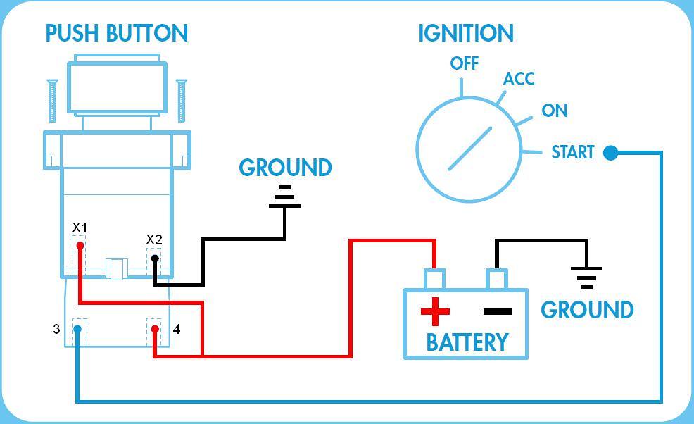
Push button start diagram. start stop push button wiring diagram - You will want a comprehensive, professional, and easy to understand Wiring Diagram. With this sort of an illustrative manual, you are going to have the ability to troubleshoot, prevent, and complete your projects without difficulty. THIS IS MY MOST VIEWED VIDEO!!! Use my Amazon links to buy whatever you need!!WE HIT 1000 SUBS!!! NOW LIKE THE VIDEO HAHAHAWe go step by step in wiring up a ... The-Honda-Maven. I had review this diagram, and like to show you a correct diagram, with timer inhibitor relay, to prevent re-start if someone re-push engine start buttom again. I had DIY my FD by using Omron Timer relay, H3y-2 12VDC 30sec. after installed, I found timer good set at 10 sec, within 10 sec we shall push bottom to start engine, if ... and Start button placement. 2 GO KEYLESS TM Intelligent Push Button Start even lets you choose how you would like to configure the systems operaticn *See Diagrams Custom, Hot rod or Vintage vehicles The 2 GO KEYLESSTM Intelligent Push Button adds an elegant twch of technology to any vehicle.
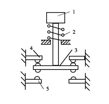
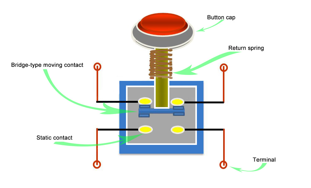
and start the vehicle even if it is already running. In Tachless Mode to start the vehicle: 1. Insert key and turn it to the "ON" position 2. Press and hold the Start/Stop button until the motor is running 3. Once the motor starts to run release the Start/Stop button To stop the vehicle: 1. Place foot on brake 2. Aug 18, 2020 · What is the internal structure diagram of the push button switch? From: Quisure 2020-08-19 The push button switch is divided into start button (green button), stop button (red button) and compound push button switch (the color is not necessarily), and the different functions are determined by the position of the internal bridge-type moving contact . Push button Starter Switch Wiring Diagram. simple wiring for toggle switch and push button start this is how to run wiring for a toggle on off switch and a push button start this is the most basic wiring you need to run your mower 800 2 0 typical wiring diagrams for push button control typical wiring diagrams for push button control push button circuit wiring diagram 0 0 4 multi station with ... How to wire a push button start diagram. L the schematic or line diagram includes all the components of the control circuit and indicates their. My ignition took a crapthink the amperage on the push switch is a 20amp. Otherwise you could use a maintained contact switch to provide control power to the coil.
Wiring Diagram for Push button Start - wiring diagram is a simplified up to standard pictorial representation of an electrical circuit. It shows the components of the circuit as simplified shapes, and the gift and signal links between the devices. A wiring diagram usually gives guidance very nearly the relative approach and concurrence of ... For example, a push button in the shape of a mushroom and red in color informs the user that the intention of the push button is to serve as an emergency stop, as shown in figure 2, unlike a push button that is simply red to indicate stop and/or green to indicate start. Fig.2: Emergency Stop Button. Push buttons are designed to function the ... start 3 start start ... transceiver class 9005 type ft fiber optic push button, selector switch, limit switch, etc. fiber optic cable electrical connections boundary seal to be in accordance with article 501-5 of the national ... table 1 standard elementary diagram symbols switches selectors push buttons - momentary contact push buttons ... Figure 5 Control for Jog or Run Using Stop Push Button and Jog-Run Selector Push Selector Switch. Selector Push Contacts are Shown for “Run” (Three Wire Operation). Rotate Switch Sleeve and Selector Contact Opens Between “2” and “Stop” Button (Two Wire Operation) Figure 6 Three Wire Control for Jogging, Start, Stop Using Push Buttons
Multiple Push Button Stations. Three Wire Control Multiple Stations – Push Button Start Wiring Diagram. Wiring Diagram contains numerous comprehensive illustrations that display the relationship of assorted products. It includes instructions and diagrams for various types of wiring strategies as well as other items like lights, windows, and ...
control circuit until the START button is pressed once again. L3 % T3 t Three Wires Three wjfes lead from the p/lot devtce to thestarter. "Undervoltage protection" and "three-wrre" control should brmg to mrnd a START-STOP push button stat/on whrch the most common means of provrdrng this type control.
Push Button Start Stop Switch Wiring Diagram – Electricity Site – Push Button Starter Switch Wiring Diagram. Wiring Diagram comes with a number of easy to stick to Wiring Diagram Guidelines. It’s meant to help each of the average user in developing a proper system. These guidelines will probably be easy to grasp and use.
This video in single push button on off wiring diagram . in Hindi ,YouTube me channel Name (khatu shyam plc program and shyam plc program.) All video used i...
tap of the push -start button will START (crank) the engine automatically until it reaches the programmed Tach value (Engine Tach Input required, see Tach Ignition Programming). Under Tachless Mode, it allows the user to press -and -hold the push -start button to manually START (crank) the engine for as long as the button being pressed.
Push Button Starter Switch Wiring Diagram – push button ignition switch wiring diagram, push button start switch wiring diagram, push button starter switch wiring diagram, Every electrical arrangement consists of various distinct parts. Each component ought to be placed and linked to other parts in specific manner. Otherwise, the arrangement won’t work as it ought to be.

Jtron Car Engine Start Push Button Ignition Switch Red Led 12v 50a Ignition Starter Button Switch Momentary Switch
This is how the ladder diagram looks for a simple start/stop function. The function can be used to start and stop anything like a motor start/stop. In this ladder logic example, there are two inputs. "Start button" or PLC input I0.0. "Stop button" or PLC input I0.1. The start button will activate the relay, or ladder logic relay M10.0.
1. Connect Push Button Switch Harness Connectors to the Push Button Switch Terminals (See Figure 1). 2. Mount the Push Button Switch to an interior location in the vehicle. The switch has been designed to mount into a 7/8 inch diameter hole. 3. NOTE: The tan and gray wires are connected to the mating wires on the main wire harness.
Size: 260.74 KB. Dimension: 1200 x 1123. Collection of start stop push button station wiring diagram. Click on the image to enlarge, and then save it to your computer by right clicking on the image. Furnas Start Stop Switch Wiring WIRE Center •. Start Stop Push button Station Wiring Diagram Unique Triumph.

Easyguard Ec003 Push Button Start Stop Remote Starter Pasif Entri Tanpa Kunci Alarm Mobil Systrm Buy Tanpa Kunci Masuk Pke Alarm Mobil Mulai Remote Product On Alibaba Com
module and Start button placement. 2 GO KEYLESS™ Push Button Start Accessory module even lets you choose how you would like to configure the systems operation. *See Installation Diagrams Custom, Hotrod or Vintage vehicles The 2 GO KEYLESS™ Push Button Start adds an elegant touch of technology to any vehicle.
Universal System**. 1. Keyless push button start. 2. Immobilizer function, will not allow the engine to start without first using the RFID Key tag. 3. Passive arming (arms automatically after 30 seconds) 4. Anti-scan, anti-grab code system.
Start stop push button wiring diagram. How does vfd start stop wiring diagram work. A wiring diagram is a type of schematic which makes use of abstract pictorial symbols to show all the interconnections of components in a system. I need help wiring the following diagram.
Typical Wiring Diagrams For Push Button Control Stations Start-Stop Control Wiring Diagrams 4 SINGLE STATION - MAINTAINED CONTACT PUSH BUTTONS t-----t L1 UNDERVOLTAGE RELEASE O.L. L2 i-c-[ START I I1 I 1 I I lr\ 0 I /;: $77 I I I I I I; STOP! L-m,----e- 1 The START button mechanically maintains the contacts that take the place of hold-in contacts.
Push button start stop switch wiring diagram electricity site push button starter switch wiring diagram. Pilot light l2 4 2 3 pilot light start stop bulletin 1495 normally closed auxiliary contacts are required. A wiring diagram is a streamlined standard photographic representation of an electrical circuit. The start button is normally open and ...
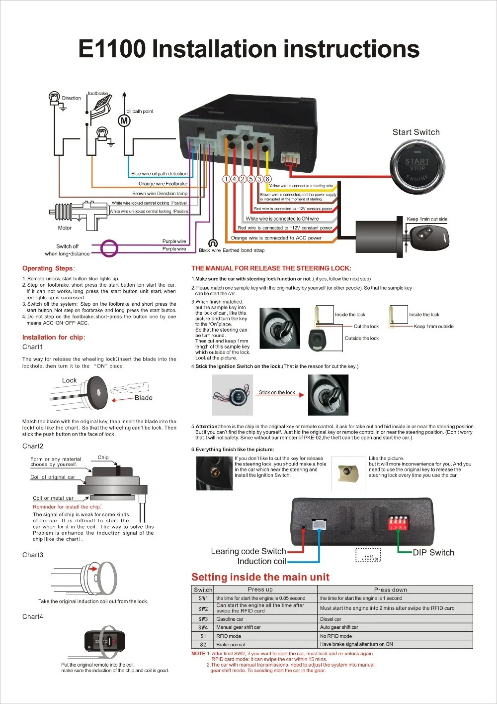
Ovi Sistem Alarm Mobil Pintar Rfid Dengan Tombol Saklar Pengapian Nyala Mati Mesin Buy Sistem Alarm Mobil Pintar Mesin Mulai Stop Button Pengapian Saklar Push Button Product On Alibaba Com
Start Stop Push button Wiring Diagram Single Phase - One of the most hard automotive repair tasks that a mechanic or fix shop can endure is the wiring, or rewiring of a car's electrical system.The difficulty essentially is that all car is different. considering grating to remove, replace or repair the wiring in an automobile, having an accurate and detailed Start Stop Push button Wiring ...
A smart start interlock is a handheld device that is wired into your cars ignition system which prevents the car from starting if you fail a breath test. Smart start ignition interlock device reviews. Michigan corporate office is racist. Diagrams are provided for installations with and without an interlock switch connection.
REMOTE/PUSH BUTTON START TECH SUPPORT: 503.693.1918 WWW.AUTOLOC.COM 2 Time Settings Recommended defaults: 1. Press button 1 for five seconds to enter programming mode. Digital display will illuminate. 2. Press buttons 2 or 3 to scroll through modes. Press button 1 to choose the desired mode to change. (1 through 9) The chart below shows ...
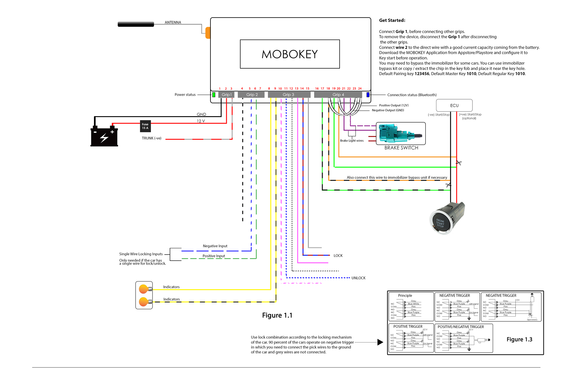


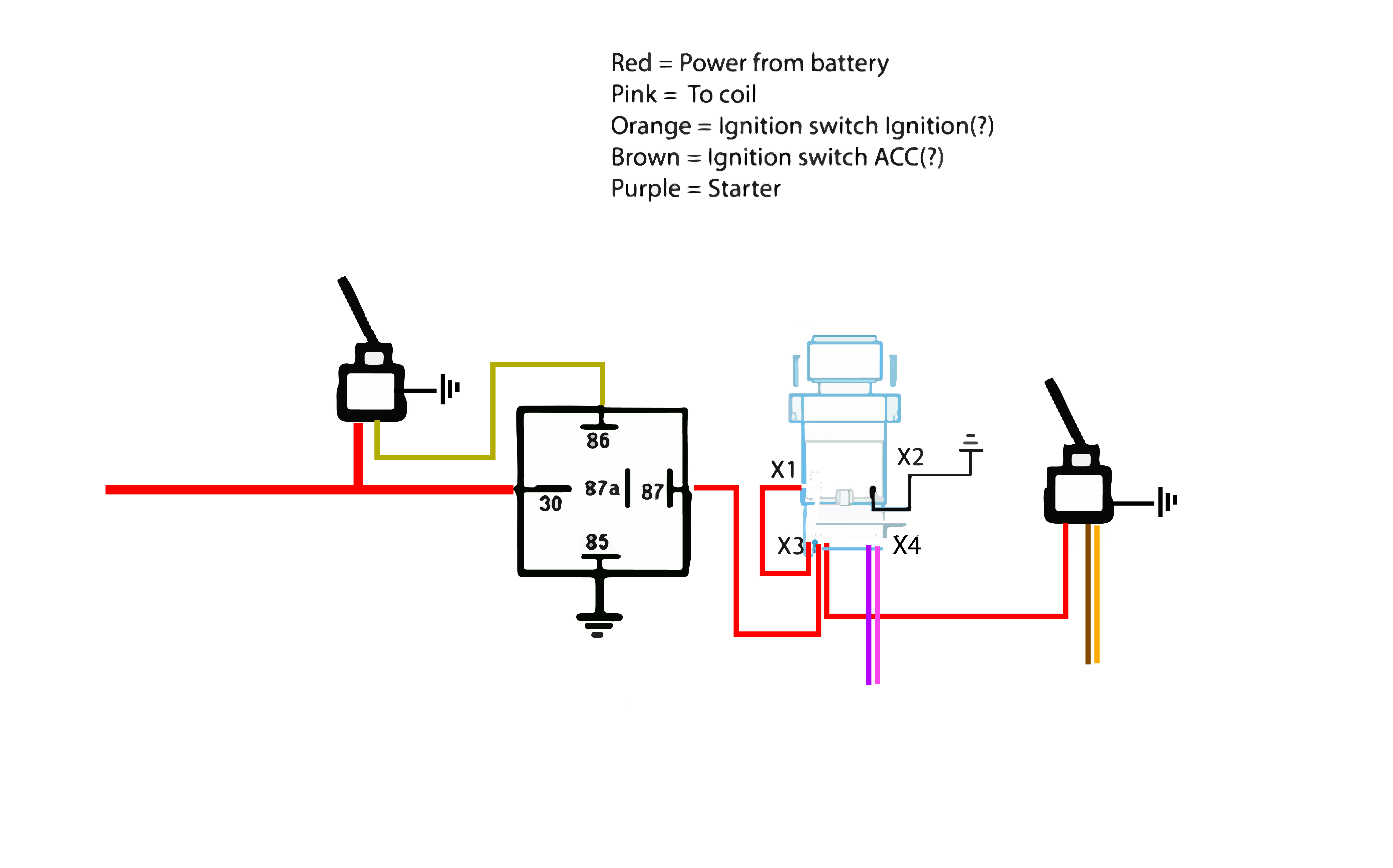


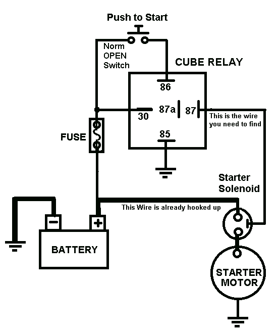




0 Response to "38 push button start diagram"
Post a Comment