37 honeywell gas valve wiring diagram
24.11.2018 · Kubota Fuel Shut Off Solenoid Wiring Diagram, in addition agco tractor keeps burning up 2 as well as tuning up a ve injection pump r along with watch together with woodward fuel shut off solenoid wiring in addition watch in addition john deere e wiring diagram moreover wiring diagram mahindra max 25 moreover gas solenoid valve wiring diagram together with wiring diagram for fuel. Honeywell VisionPro 8000 as All Fuel Kit Control Wiring Heat Pump Honeywell VisionPro 8000 Standard Furnace 24 Volt+ Fan Only Operation Air Conditioning 1st Stage Gas Heat AC Reversing Valve Common Outdoor Temp Sensor Outdoor Temp Sensor Control Board Low Voltage Connection 10 Some AC Systems will have a blue wire with a pink stripe in place of the yellow or Y wire. This diagram is to …
Honeywell t9 wiring diagram. Proportional control thermostats (8 pages) Thermostat Step 2. Proportional control thermostats (8 pages) Thermostat thermostat wiring installation instructions. The programmable thermostat from Honeywell started with this particular series. The thermostat has seven wires connected to terminals labeled C, R, W2, E, Y1 and W1 together (with a jumper), O/B, and G. …

Honeywell gas valve wiring diagram
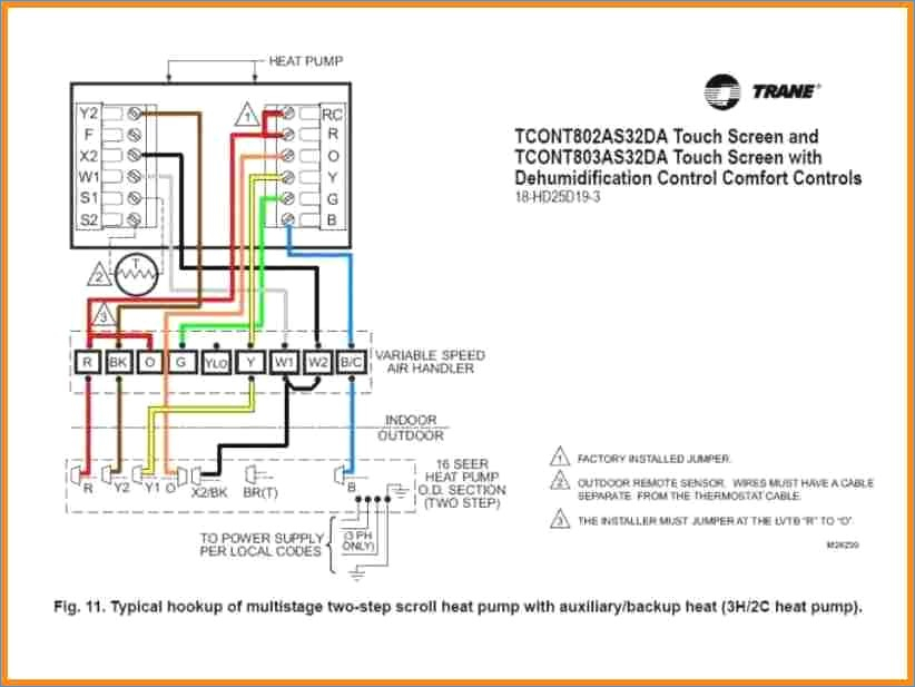
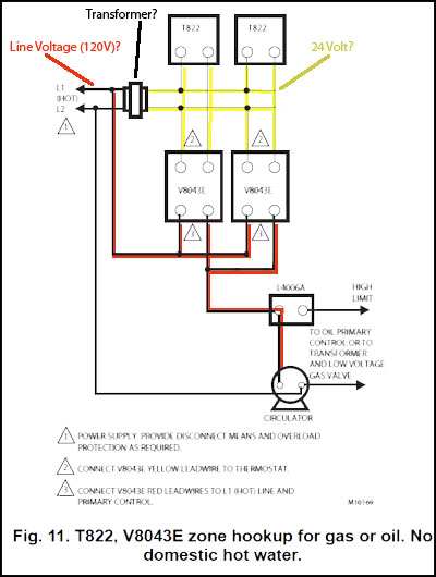
valve for cool (“O” factory setting) or heat (“B”). Wire specifications Use 18- to 22-gauge thermostat wire. Shielded cable is not required. Keep wires in this shaded area CAUTION: ELECTRICAL HAZARD. Can cause electrical shock or equipment damage. Disconnect power before wiring. Wiring Above Honeywell zone valve wiring diagrams are from Honeywell's motorized [zone] valve installation instructions [3] Watch out: when installing zone valves not to overheat the valve or its parts. We were taught to completely remove the zone valve motor and electrical parts while sweating the zone valve to the heating system piping, but even so, overheating can damage the zone valve moving ... That is a basic Honeywell thermostat wiring diagram for a single-stage heat pump. If you have a two-stage heat pump, then you will also utilize terminal Y2 for the second stage. Furthermore, this thermostat wiring diagram is specifically for a system with two transformers.Your system likely only has one transformer, as most typical residential systems only use a single transformer for control.
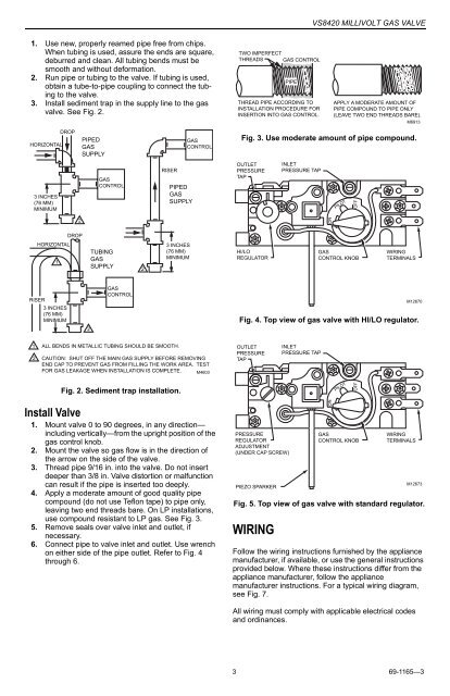
Honeywell gas valve wiring diagram. Honeywell has a scam going, I paid over $500,00 for my water heater and several hundred to have it installed, since day one I have had nothing but trouble with the Honeywell thermostat,gas valve. Its a Reliant water heater, but at Menards. You cannot find the old fashion w/heaters that you could lite and forget it. I am beyond pissed, Reliant has a warrantee but it don’t cover parts!!! Can ... This Honeywell gas valve is used in Modine PD, PAE, and PA 24 volt standing pilot heaters 300,000 to 400,000 BTU input in natural gas. Comes setup for natural gas and includes kit to convert to propane. Replaces Modine part # 5H72591-3. Can be used with larger propane models as well. Checking the wiring (5 wire) against a wiring diagram the orange wire goes to a connecting block but no further. This was a professional installation not DIY. My understanding is that the orange is normally intended as a feed to tell the boiler to fire. However the boiler fires fine and must be getting signals fom other valves within the boiler itself. What is the point of this valve in the ... Mount any required controls, such as the gas control, spark igniter, flame sensor, thermostat, limit and trans-former according to manufacturer’s instructions. WIRE THE SYSTEM CAUTION 1. Check the wiring diagram furnished by the appli-ance manufacturer, if available, for circuits differ-ing from the wiring hookups shown. Carefully
That is a basic Honeywell thermostat wiring diagram for a single-stage heat pump. If you have a two-stage heat pump, then you will also utilize terminal Y2 for the second stage. Furthermore, this thermostat wiring diagram is specifically for a system with two transformers.Your system likely only has one transformer, as most typical residential systems only use a single transformer for control. Above Honeywell zone valve wiring diagrams are from Honeywell's motorized [zone] valve installation instructions [3] Watch out: when installing zone valves not to overheat the valve or its parts. We were taught to completely remove the zone valve motor and electrical parts while sweating the zone valve to the heating system piping, but even so, overheating can damage the zone valve moving ... valve for cool (“O” factory setting) or heat (“B”). Wire specifications Use 18- to 22-gauge thermostat wire. Shielded cable is not required. Keep wires in this shaded area CAUTION: ELECTRICAL HAZARD. Can cause electrical shock or equipment damage. Disconnect power before wiring. Wiring







![[DIAGRAM] Gvrl 40 Gas Valve Diagram FULL Version HD ...](https://www.robertshaw.com/assets/0/2147483725/2147483807/2147483810/787cc71d-fa10-4f03-824b-c5b9bcc9b3d8.jpg)


0 Response to "37 honeywell gas valve wiring diagram"
Post a Comment